| 1 |
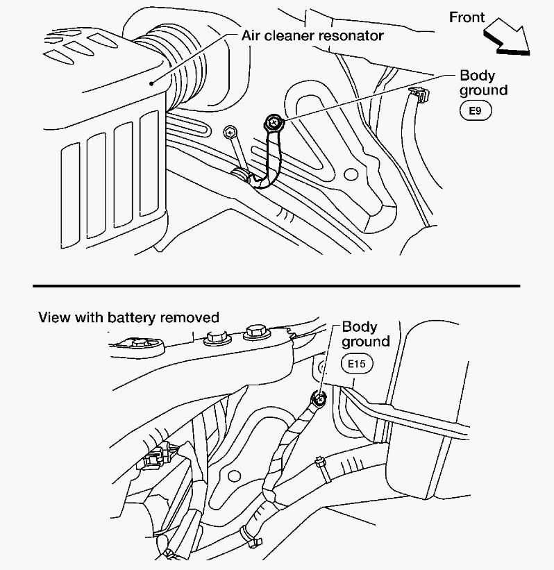
CHECK GROUND CONNECTIONS
- Turn ignition switch OFF.
- Loosen and retighten two ground screws on the body. Refer to
[POWER SUPPLY AND GROUND CIRCUIT CHECK
].
 Courtesy of SUZUKI OF AMERICA CORP. Courtesy of SUZUKI OF AMERICA CORP.
OK or NG |
GO TO 2. |
Repair or replace ground connections. |
| 2 |
RETIGHTEN AIR FUEL RATIO (A/F) SENSOR 1
Loosen and retighten the air fuel ratio (A/F) sensor 1. Refer to
[EXHAUST MANIFOLD AND THREE WAY CATALYST: REMOVAL AND INSTALLATION [QR25DE]
] |
GO TO 3. |
|
| 3 |
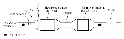
CHECK EXHAUST GAS LEAK
- Start engine and run it at idle.
- Listen for an exhaust gas leak before three way catalyst (manifold).
 Courtesy of SUZUKI OF AMERICA CORP. Courtesy of SUZUKI OF AMERICA CORP.
OK or NG |
GO TO 4. |
Repair or replace. |
| 4 |
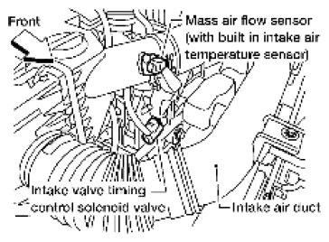
CHECK FOR INTAKE AIR LEAK
Listen for an intake air leak after the mass air flow sensor.
OK or NG |
GO TO 5. |
Repair or replace. |
| 5 |
CLEAR THE SELF-LEARNING DATA
- With SDT
- Start engine and warm it up to normal operating temperature.
- Select "SELF-LEARNING CONT" in "Utility" mode with SDT.
- Clear the self-learning control coefficient by touching "Clear" or "START".
- Run engine for at least 10 minutes at idle speed.
Is the 1st trip DTC P0171 or P0172 detected?
Is it difficult to start engine?
- Without SDT
- Start engine and warm it up to normal operating temperature.
- Turn ignition switch OFF.
- Disconnect mass air flow sensor harness connector.
 Courtesy of SUZUKI OF AMERICA CORP. Courtesy of SUZUKI OF AMERICA CORP.
- 4. Restart engine and let it idle for at least 5 seconds.
- 5. Stop engine and reconnect mass air flow sensor harness connector.
- 6. Make sure DTC P0102 is displayed.
- 7. Erase the DTC memory. Refer to
[EMISSION-RELATED DIAGNOSTIC INFORMATION
].
- 8. Make sure DTC P0000 is displayed.
- 9. Run engine for at least 10 minutes at idle speed.
Is the 1st trip DTC P0171 or P0172 detected?
Is it difficult to start engine?
Yes or No |
Perform trouble diagnosis for DTC P0171 or P0172. Refer to DTC P0171: Fuel Injection System Function
or DTC P0172: Fuel Injection System Function
. |
GO TO 6. |
| 6 |
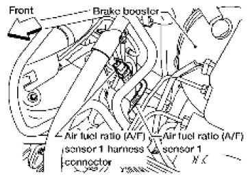
CHECK AIR FUEL RATIO (A/F) SENSOR 1 POWER SUPPLY CIRCUIT
- Turn ignition switch OFF.
- Disconnect A/F sensor 1 harness connector.
 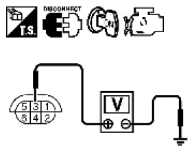 Courtesy of SUZUKI OF AMERICA CORP.SUZUKI OF AMERICA CORP. Courtesy of SUZUKI OF AMERICA CORP.SUZUKI OF AMERICA CORP.
- 3. Turn ignition switch ON.
- 4. Check voltage between A/F sensor 1 terminal 3 and ground with SDT or tester.
Courtesy of SUZUKI OF AMERICA CORP.SUZUKI OF AMERICA CORP.
Voltage: Battery voltage
OK or NG |
GO TO 8. |
GO TO 7. |
| 7 |
DETECT MALFUNCTIONING PART
Check the following.
- Harness connectors E2, F32
- IPDM E/R harness connector E119
- 15A fuse (No. 54)
- Harness for open or short between A/F sensor 1 and fuse
|
Repair or replace harness or connectors. |
|
| 8 |
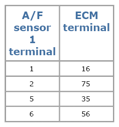
CHECK A/F SENSOR 1 INPUT SIGNAL CIRCUIT FOR OPEN AND SHORT
- Turn ignition switch OFF.
- Disconnect ECM harness connector.
- Check harness continuity between the following terminals. Refer to WIRING DIAGRAM
.
 Courtesy of SUZUKI OF AMERICA CORP. Courtesy of SUZUKI OF AMERICA CORP.
Continuity should exist.
- 4. Check harness continuity between ECM terminals 16, 35, 56, 75 or A/F sensor 1 terminals 1, 2, 5, 6 and ground. Refer to WIRING DIAGRAM
.
Continuity should not exist.
- 5. Also check harness for short to power.
OK or NG |
GO TO 9. |
Repair open circuit, short to ground or short to power in harness or connectors. |
| 9 |
CHECK AIR FUEL RATIO (A/F) SENSOR 1 HEATER
Refer to
[P0031, P0032 A/F SENSOR 1 HEATER ].
OK or NG |
GO TO 10. |
GO TO 13. |
| 10 |
CHECK MASS AIR FLOW SENSOR
Refer to
[P0101 MAF SENSOR ].
OK or NG |
GO TO 11. |
Replace mass air flow sensor. |
| 11 |
CHECK PCV VALVE
Refer to
[POSITIVE CRANKCASE VENTILATION CIRCUIT CHECK
].
OK or NG |
GO TO 12. |
Repair or replace PCV valve. |
| 12 |
CHECK INTERMITTENT INCIDENT
Perform
[SERVICE INFORMATION FOR ELECTRICAL INCIDENT: INTERMITTENT INCIDENT
]
OK or NG |
GO TO 13. |
Repair or replace. |
| 13 |
REPLACE AIR FUEL RATIO (A/F) SENSOR 1
Replace air fuel ratio (A/F) sensor 1. Refer to [EXHAUST MANIFOLD AND THREE WAY CATALYST: EXPLODED VIEW [QR25DE]
].
CAUTION:
- Discard any air fuel ratio (A/F) sensor which has been dropped from a height of more than 0.5 m (19.7 in) onto a hard surface such as a concrete floor; use a new one.
- Before installing new air fuel ratio (A/F) sensor, clean exhaust system threads using Heated Oxygen Sensor Thread Cleaner [commercial service tool (J-43897-18 or J-43897-12)] and approved anti-seize lubricant (commercial service tool).
|
INSPECTION END |
|