Ignition System Component Overview
- For trouble free operation of the electrical components a voltage of at least 11.5 volts is necessary.
- It is possible that the Engine Control Module (ECM) will recognize a malfunction and store a Diagnostic Trouble Code (DTC) during some tests. After completing all checks and repairs, check the DTC memory and erase the memory, if necessary. Refer to the vehicle diagnostic tester.
- If the engine only starts briefly and then turns off again after troubleshooting, repairs or checking of the components, it may be that the immobilizer is blocking the ECM. The ECM may have to be adapted. Refer to "Guided Functions" in the vehicle diagnostic tester.
 Courtesy of VOLKSWAGEN GROUP OF AMERICA, INC.
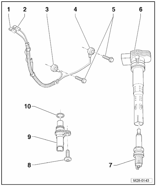
- Knock Sensor 2 Connector
- Gray
- Contacts are gold plated.
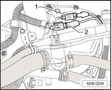
- Installed position, refer to Fig 2.
- Knock Sensor 1 Connector
- Green
- Contacts are gold plated.
- Installed position, refer to Fig 2.
- Knock Sensor 2 -G66-
- Note the installed position: The wire connection points 45° toward the right on the outside.
- Knock Sensor 1 -G61-
- Note the installed position: The wire connection points downward vertically.
- Bolt
- 20 Nm
- The tightening specification affects the function of the knock sensor.
- Ignition Coil with Power Output Stage -N70, N127, N291, N292, N323-
- Spark Plug
- Bolt
- Camshaft Position Sensor -G40-
- Contacts are gold plated.
- O-ring
- No replacement part available.
 Courtesy of VOLKSWAGEN GROUP OF AMERICA, INC.
- Green for the knock sensor 1
- Gray for the knock sensor 2