Electrical And Electronic Components And Locations: Notes
 Courtesy of VOLKSWAGEN GROUP OF AMERICA, INC.
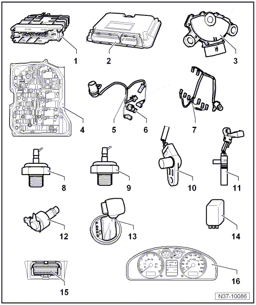
- Transmission Control Module -J217-
- The control module sends and receives data from the Data bus.
- Installed location for the Jetta MY 05 through 10, Jetta SportWagen (US)/Jetta Wagon (Canada) MY 09, Jetta SportWagen (US)/Golf Wagon (Canada) from MY 10. Refer to Transmission Control Module, Jetta MY 05 through 10, Jetta SportWagen (US)/Jetta Wagon (Canada) MY 09, Jetta SportWagen (US)/Golf Wagon (Canada) from MY 10
.
- Installed location for the Jetta, from MY 11, with a 2.0 L engine. Refer to Transmission Control Module, Jetta from MY 11, with a 2.0 L Engine
.
- Installed location for the Jetta, from MY 11, with a 2.5 L engine. Refer to Transmission Control Module, Jetta from MY 11, with a 2.5 L Engine
.
- Can be checked in "Guided Fault Finding" using the VAS 5051.
- Engine Control Module
- Multifunction Transmission Range Switch -F125-
- Valve Body
- Installed location, refer to Valve Body
.
- The components can be checked in "Guided Fault Finding" using the VAS 5051.
- 8 Pin Wiring Harness
- Transmission Fluid Temperature Sensor -G93-
- Installed location, refer to 8 Pin Wiring Harness
- Can be checked in "Guided Fault Finding" using the VAS 5051.
- 14 Pin Wiring Harness
- Automatic Transmission Hydraulic Pressure Sensor 1 -G193-
- Automatic Transmission Hydraulic Pressure Sensor 2 -G194-
- Transmission Input Speed Sensor -G182-
- Transmission Output Speed Sensor -G195-
- Shift Lock Solenoid -N110-
- Installed location: The shift lock solenoid is located in the selector mechanism.
- Can be checked in "Guided Fault Finding" using the VAS 5051.
- Tiptronic Switch -F189-
- Installed location, refer to Tiptronic Switch
.
- Can be checked in "Guided Fault Finding" using the VAS 5051.
- Terminal 50 Power Supply Relay -J682-
- Inside the engine compartment E-box.
- Refer to appropriate information in the System Wiring Diagram WIRING
.
- Diagnostic Connection
- Transmission Range Display -Y6-