Battery, Transmitter And Receiver Unit, Fuse And Wiring Harness, Overview
 Courtesy of VOLKSWAGEN UNITED STATES, INC.
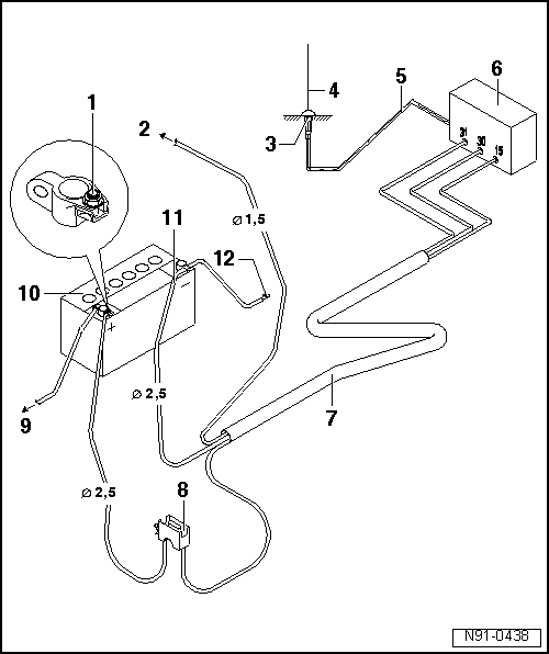
- 1 - Positive Connection
- Red wire with suitable connection.
- 2 - To Terminal 15a
- Connection to terminal 15a. Refer to the appropriate SYSTEM WIRING information.
- Ensure wire is protected by fuse.
- Fuse maximum 15 amps.
- 3 - Antenna Ground
- Ensure correct ground connection to body.
- Antenna location must be treated with suitable corrosion protection.
- 4 - Transmitting/Receiving Antenna
- 5 - Shielded Antenna Wire
- Wire with coaxial connector.
- 6 - Telephone Or Two-Way Radio Transmitter/Receiver Unit
- 7 - Wiring Harness
- Voltage supply positive via red wire, 2.5 mm2
cross section.
- Voltage supply negative via brown wire, 2.5 mm2
cross section.
- If necessary, wire to terminal 15a via black wire 1.5 mm 2
cross section.
- 8 - Fuse Holder
- 9 - To Starter
- 10 - Battery
- Installation location in engine compartment.
- 11 - Negative Wire
- 12 - Body Ground