Assembly
The assembly procedure is not in sequential steps, but grouped in sub-assemblies.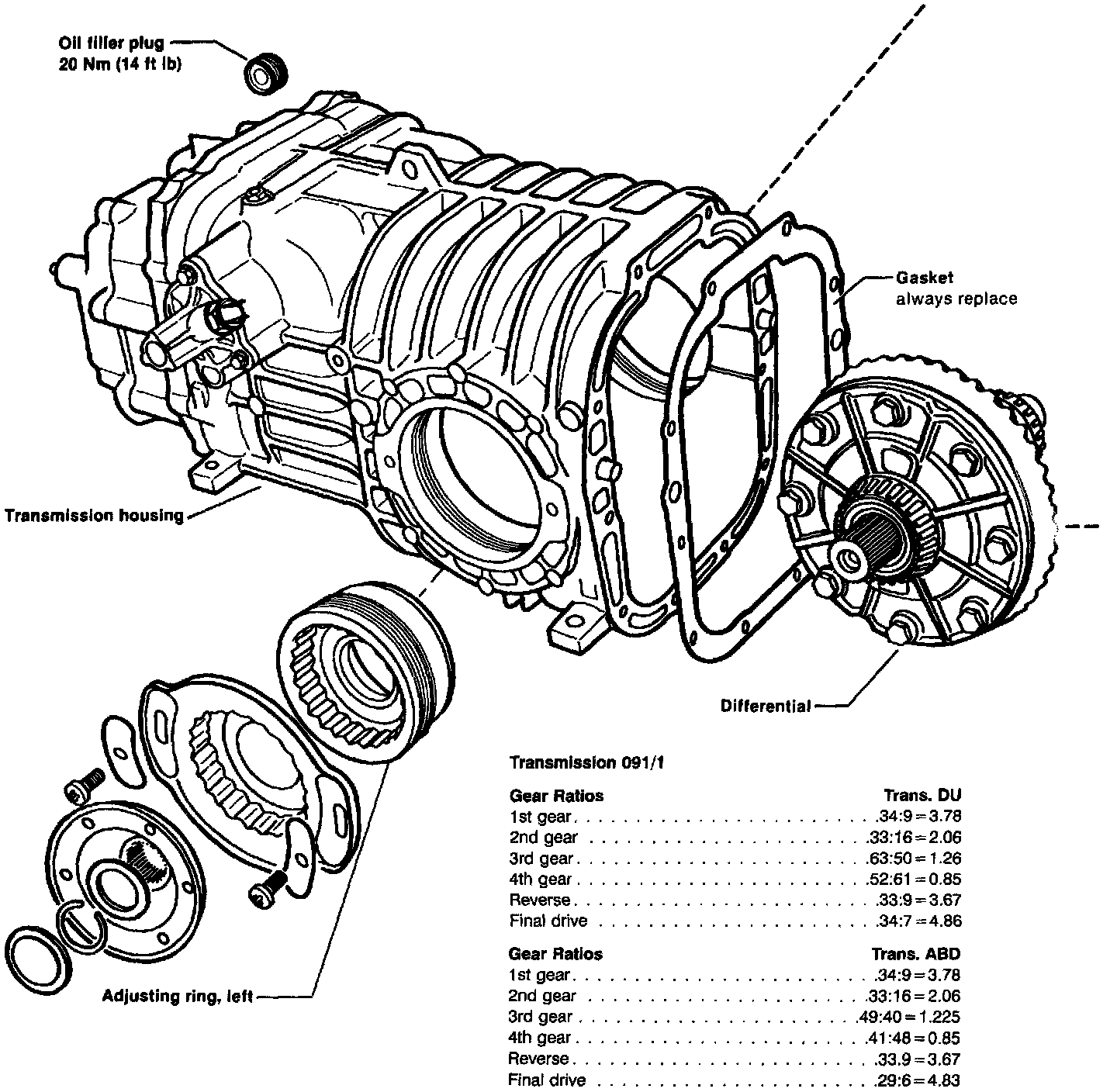
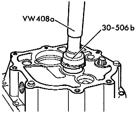
Drive Flange and Adjusting Ring Installation
- Install left and right adjusting rings and align marks at depth previously measured
- Lubricate threads with MoS2 grease
CAUTION: Do not tighten left side adjusting ring until clutch housing has been installed and bolts torqued.
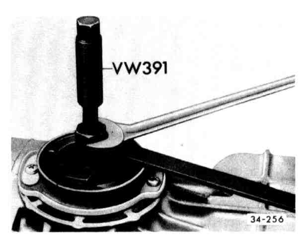
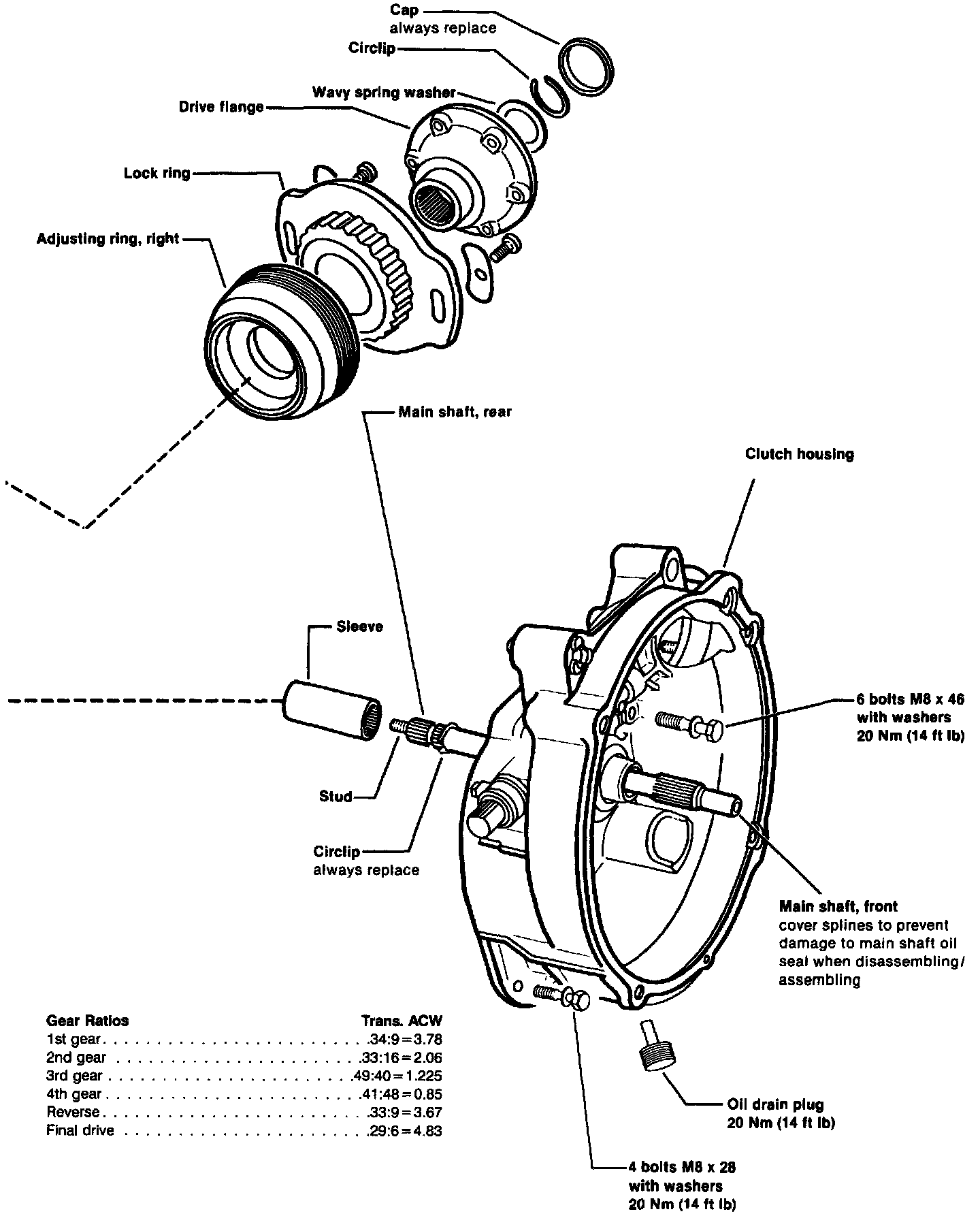
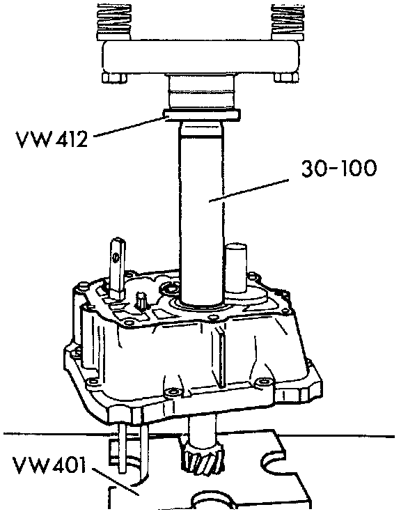
- Install drive flange using VW 391
- Insert wave washer
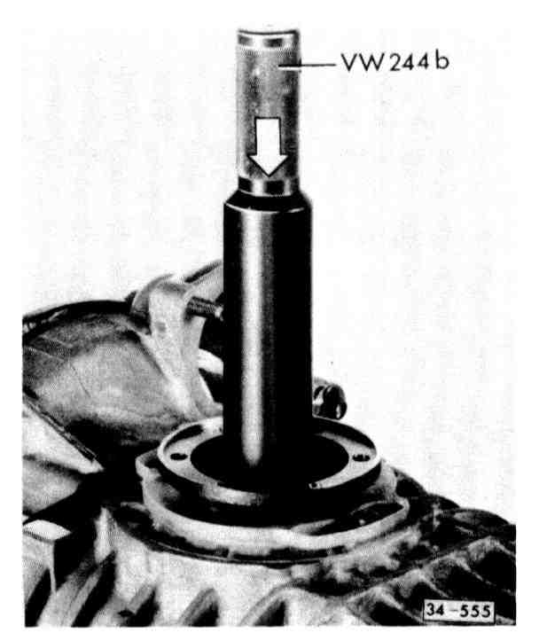
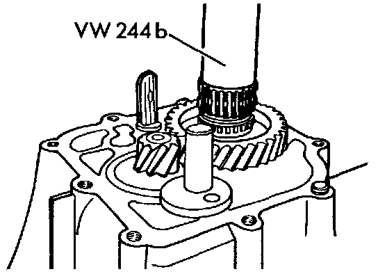
- Press circlip into groove with VW 244b and at same time check that washer is centered
Rear Main Shaft Installation
- Screw front and rear main shafts together then back off one spline
- Push reverse gear on and install new circlip
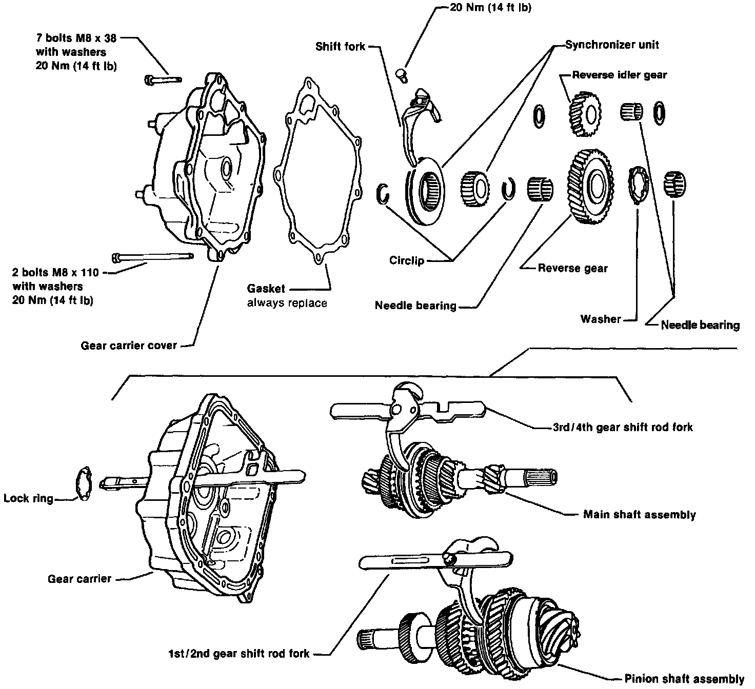
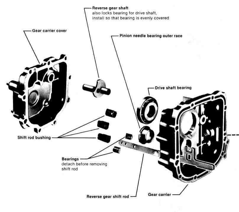
Gear Carrier/Gearshift Housing Assembly
- Press main shaft with shift rod into gear carrier
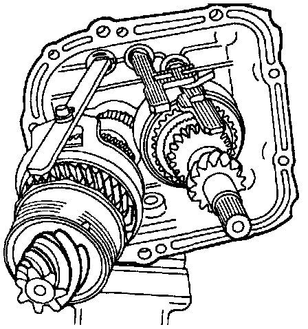
- Install pinion shaft with shift rod
- Shift into 3rd gear
- Shift into neutral
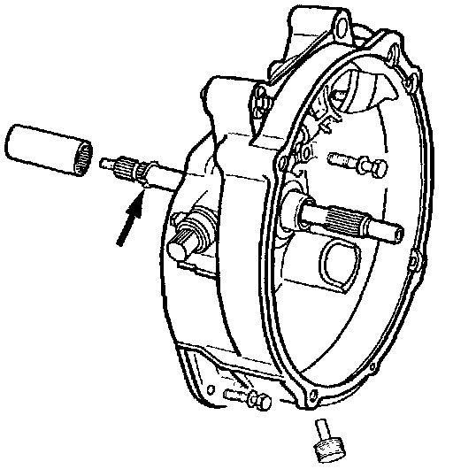
- Install pinion shaft needle bearing
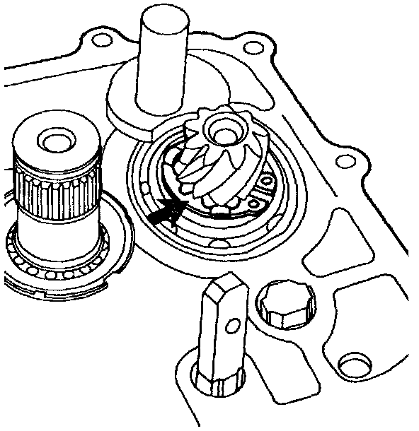
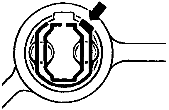
- Install circlip
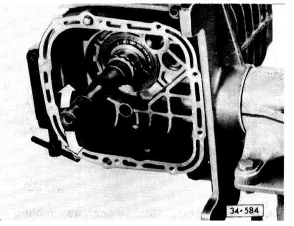
- Make sure lugs at circlip are below teeth of pinion head (arrow)
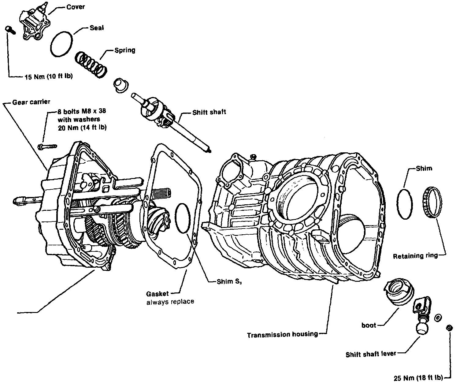
- Install shim S3
- Install new gasket
- Align shift rod
- Align flat on piston with recess in housing
- Tap on pinion with plastic hammer to install
- Make sure teeth of gears match properly
- Install retaining ring and tighten to 225 Nm (162 ft lb) then loosen and retighten to 225 Nm (162 ft lb)
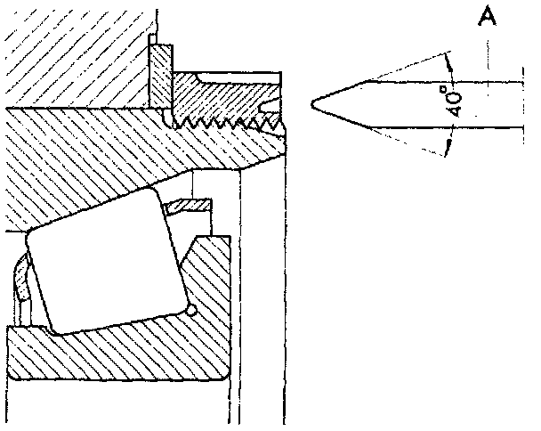
- Peen retaining ring twice with suitable tool A (local manufacture)
- Attach gear carrier to transmission housing and tighten bolts to 20 Nm (14 ft lb)
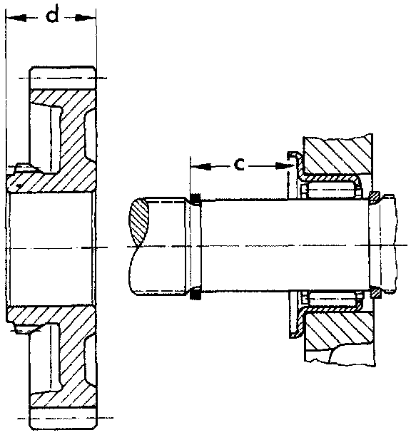
Determining Thickness Of Spacer For Reverse Gear
- Install circlip
- Measure distance C
- Calculate spacer needed
Example: Measurement c (29.1 mm)
Subtract measurement d (24.7 mm)
Equals thickness of spacer (4.4 mm)
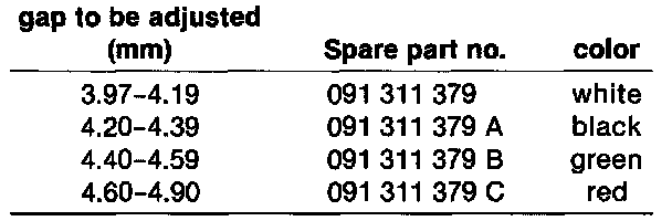
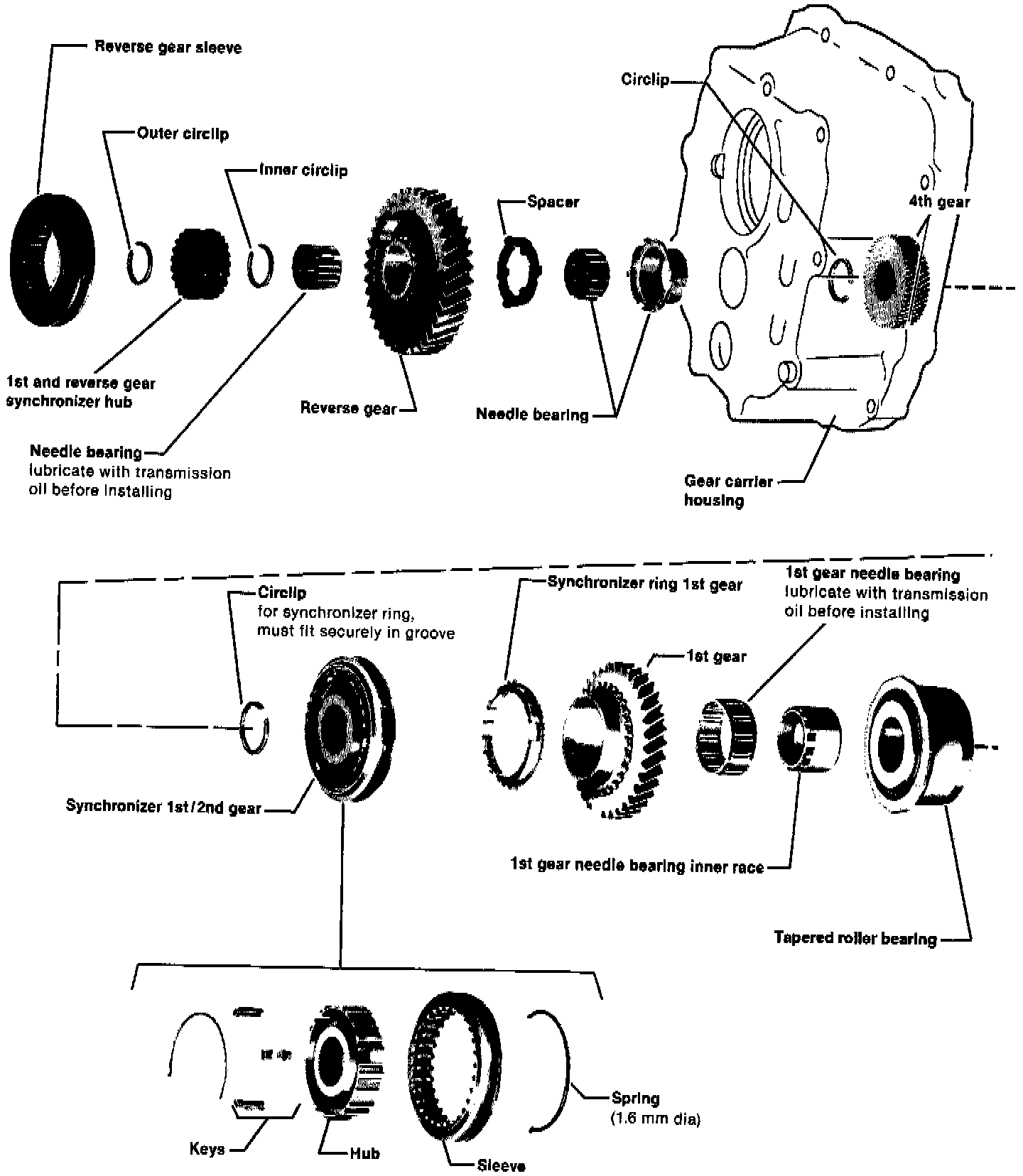
- Install spacer (selected from chart), reverse gear, needle bearing and circlip
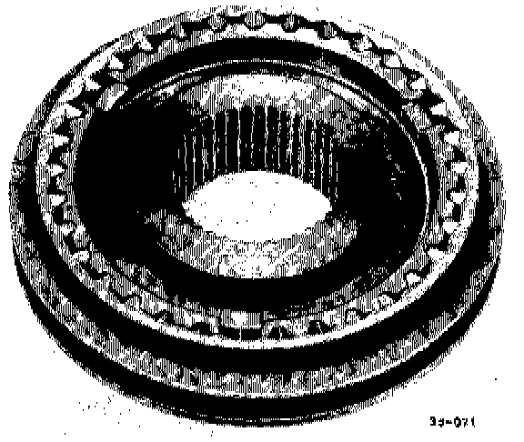
- Install synchronizer
- Install circlip
- Install reverse gear
- Groove in gear must face cover
- Install needle bearing and washers
- Install shift rod/fork bolt and tighten to 20 Nm (14 ft lb)
- Before installing, coat thread of bolt with D6-locking compound
- Install new gasket
- Install cover
- Align shaft and bore in cover
- Tighten bolts to 20 Nm (14 ft lb)
- Install shift shaft
- Slotted side toward differential housing
- Install new gasket
- Install spring
- Install cover and tighten bolts to 15 Nm (10 ft lb)
- Install back-up light switch
- Install shift shaft lever
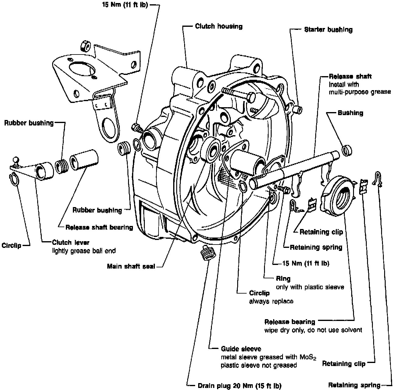
Servicing Clutch Housing Assembly
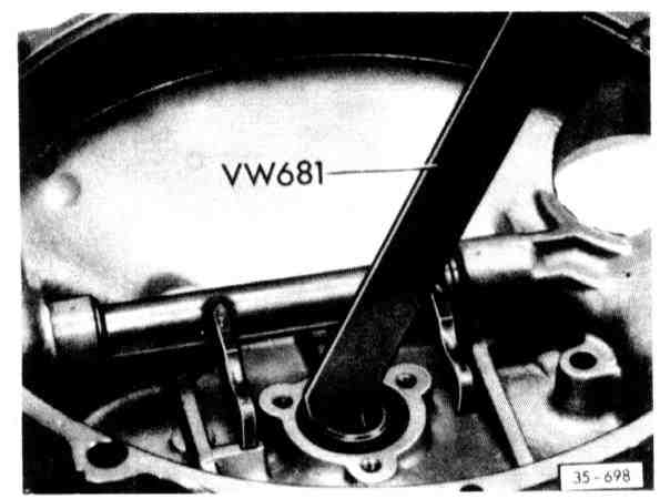
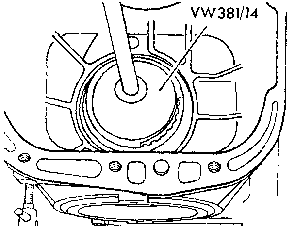
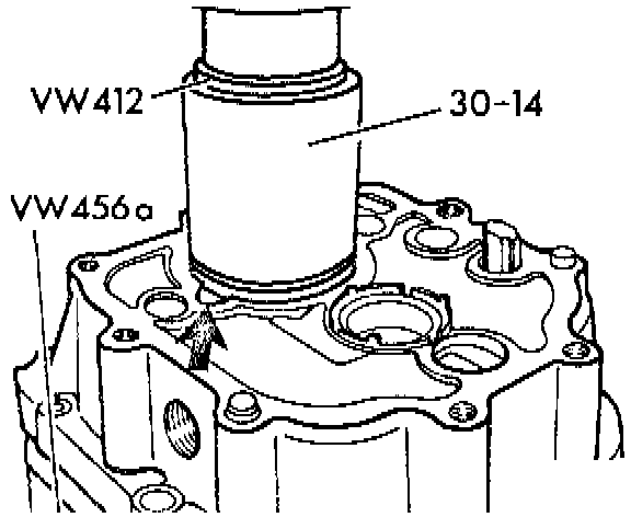
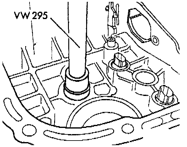
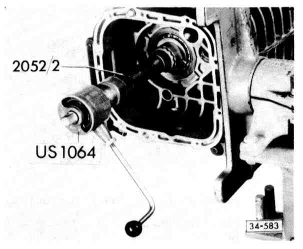
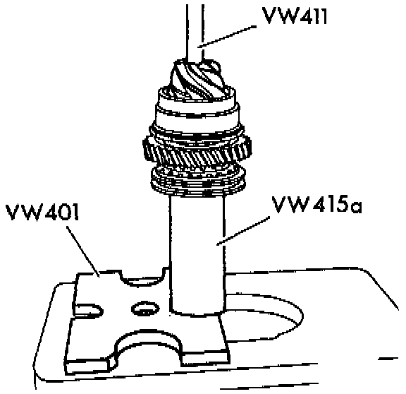
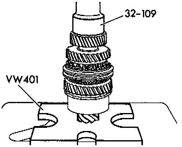
- Pry out main shaft seal using VW 681
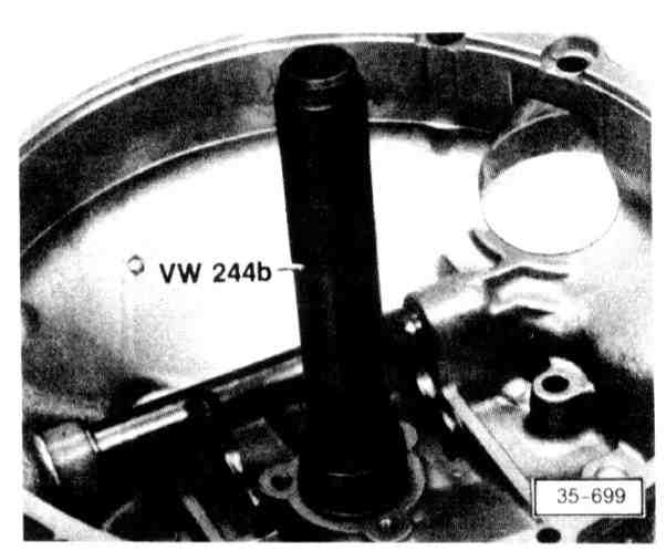
- Install main shaft seal, drive in using VW 244b
- Remove release shaft bushing, refer to image
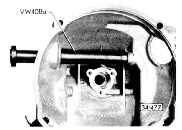
- Drive in flush

- Starter bushing can be removed and installed using VW 222a when transmission is removed
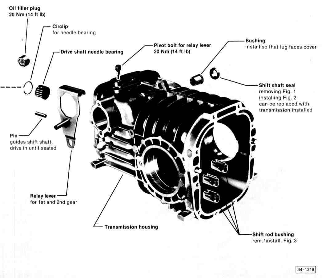
Shift Shaft Oil Seal and Shift Rod Bushings Assembly
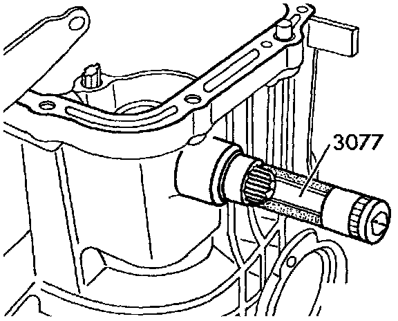
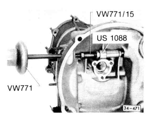
- Installing shift shaft oil seal -- refer to image
- Removing:
^ Turn bushing so that lug (arrow) is in recess of housing and press out
- Installing:
^ Align bushing and rod
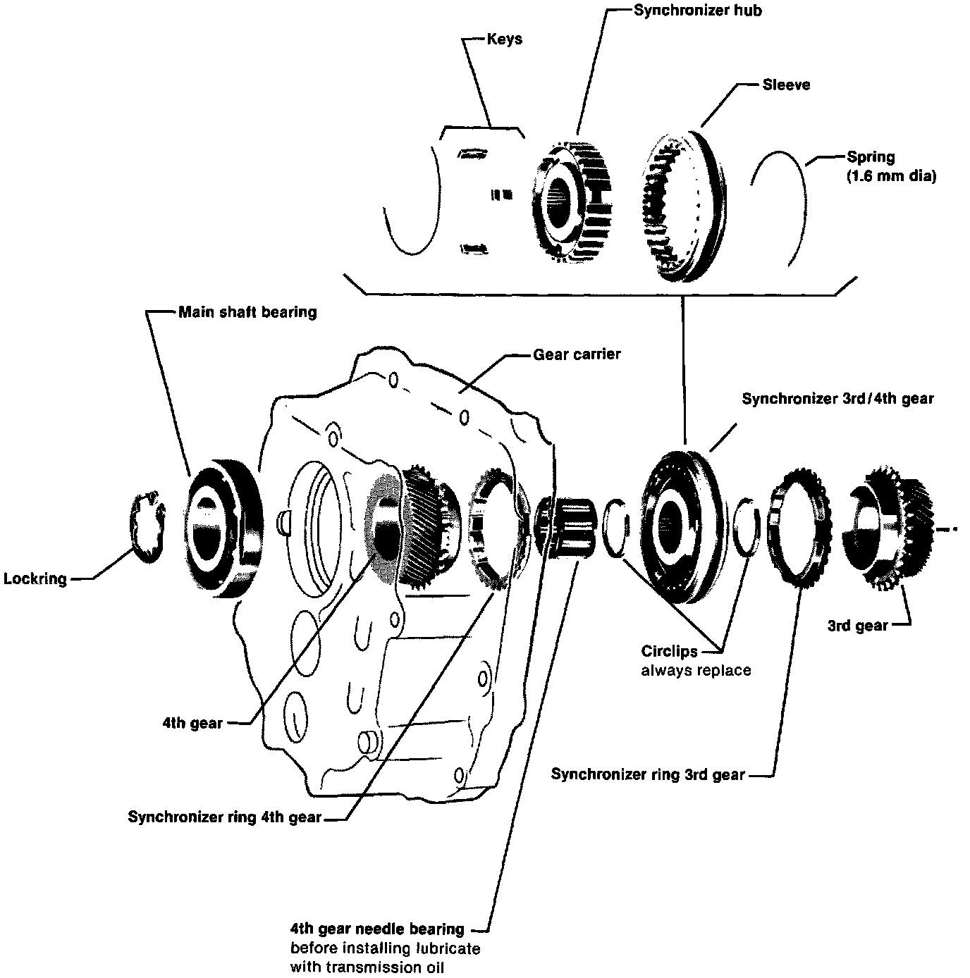
Main Shaft Assembly
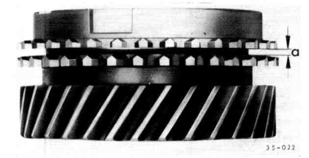
- Press synchronizer rings onto gear by hand and measure gap a with feeler gauge
^ 3rd Gear
a = New 1.25-1.95 mm (0.049-0.077 in)
Wear limit 0.5 mm (0.020in)
^ 4th gear
a = New 1.0-1.7 mm (0.039-0.067 in)
Wear limit 0.5 mm (0.020 in)
- Identification grooves (arrows A & B of sleeve and hub are on opposite sides. Groove on sleeve (arrow B) faces 4th gear
- Grooves (arrow C) are for identification:
^ 1st & 2nd gear -- 1 groove
^ 3rd & 4th gear -- 2 grooves
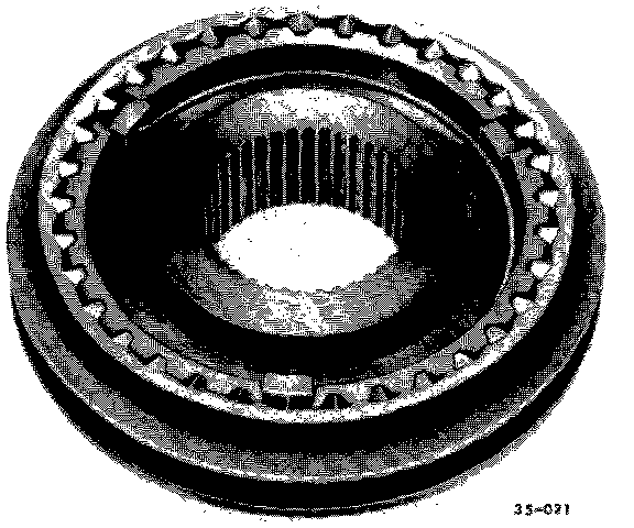
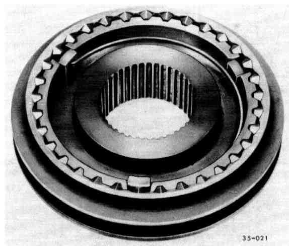
- Slide sleeve over synchronizer hub. Matched position is not necessary
- Insert keys and install springs with ends offset 120°. Angled ends of springs must fit into keys
- Turn 3rd/4th synchronizer ring until grooves are in line with keys
- Identification groove on sleeve faces 4th gear
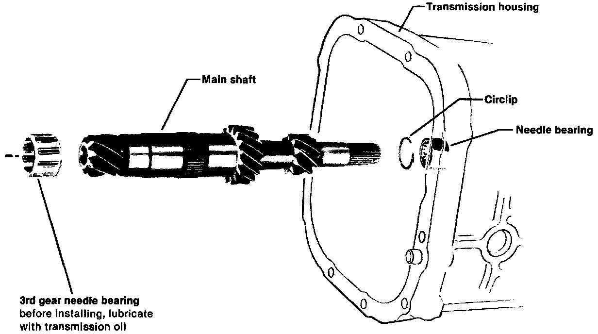
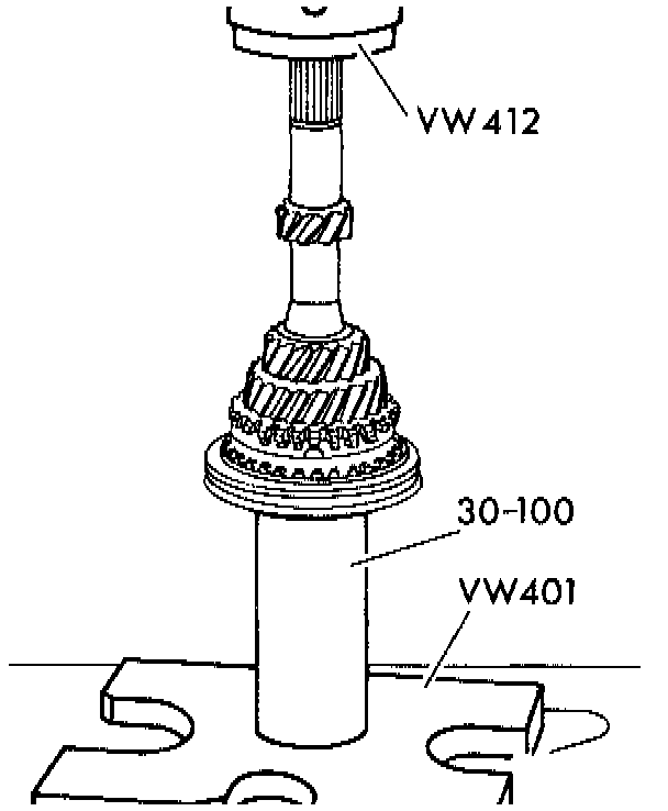
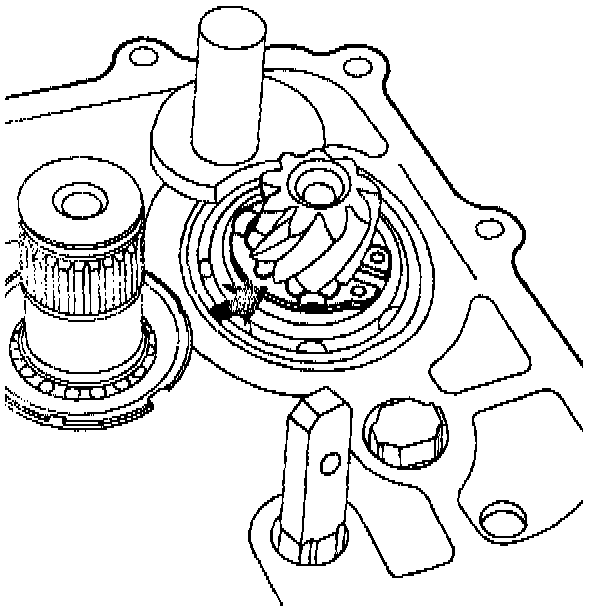
- Press in main shaft ball bearing so that recess in bearing is aligned with recess (arrow) in housing
- Install needle bearing in housing. Lettered side of bearing (thicker material) must face installing tool
- Install circlip, make sure ring is seated correctly (arrow)
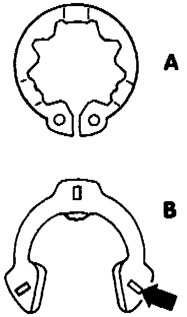
- Either of two types of circlip may be used:
^ A = previous circlip -- Part No. 091 311 381
^ B = new circlip -- Part No. 091 311 381 A
CAUTION: Always replace the circlip during repairs. Identifying marks on a new circlip (arrow) must face reverse gear splines.
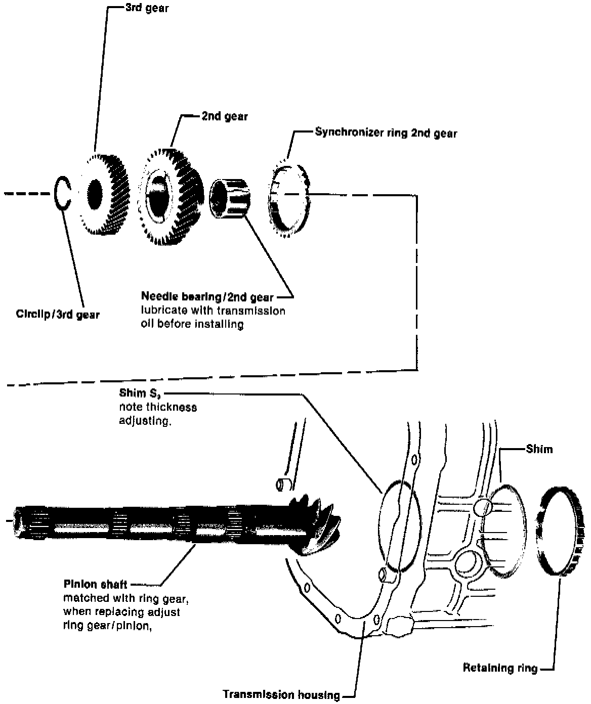
Pinion Shaft Assembly
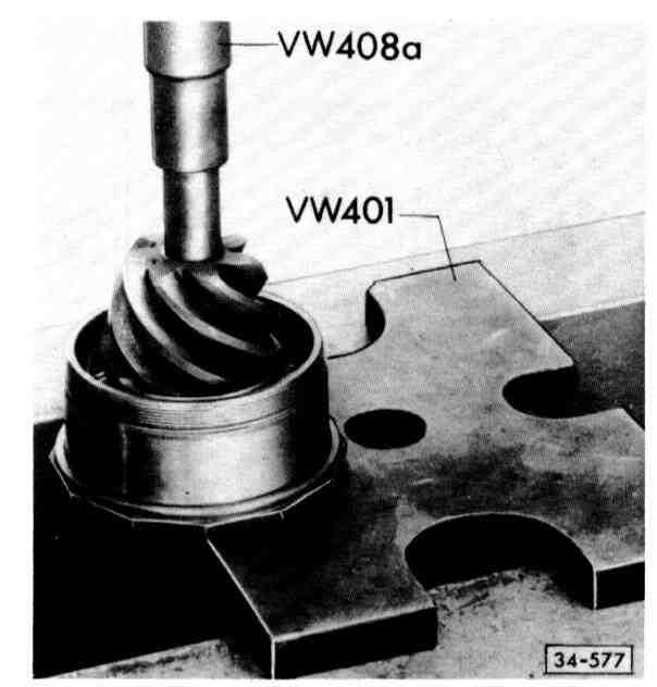
- Heat inner race of tapered roller bearing to about 100°C (212°F) and press on to pinion shaft
- Before tightening needle bearing inner race, let tapered roller bearing cool to room temperature
- Heat inner of needle bearing race to about 60°C (140°F) and screw on as far as possible by hand
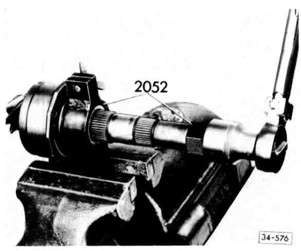
- Place pinion shaft in tool 2052 and tighten wing nut lightly
- Tighten inner race to 210 Nm (152 ft lb)
- Lubricate bearings with transmission oil and tighten retaining ring
- Turn pinion shaft in both directions about 15-20 times
- Turn further and check turning torque:
^ New bearings -- up to 210 Ncm (180 in lb)
^ Used bearings (run at least 30 miles) -- up to 70 Ncm (61 in lb)
- Check for rock at end of pinion. There must not be any detectable movement. If there is, replace tapered roller bearing
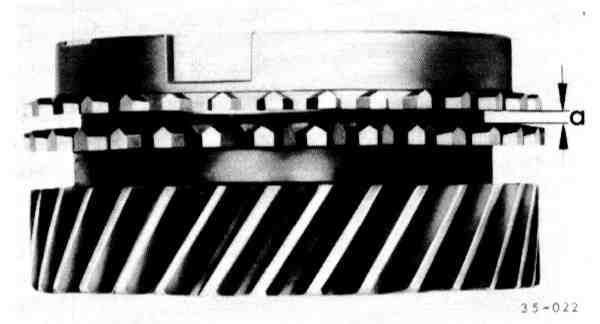
- Press 1st/2nd synchronizer rings onto gear by hand and measure gap (a) with feeler gauge
^ a = New part 1.3-1.9 mm (0.051-0.075 in)
Wear limit 0.5 mm (0.020 in)
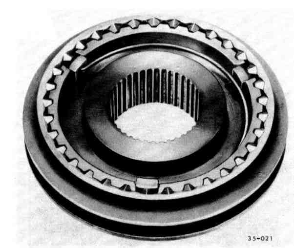
- Assemble 1st/2nd gear synchronizer
- Groove (arrow A) must face 2nd gear
- Collar on hub must face 1st gear
- Grooves (arrow B) are for identification:
^ 1st gear & 2nd gear -- 1 groove
^ 3rd gear & 4th gear -- 2 grooves
- Slide sleeve over synchronizer hub. Matched position is not necessary
- Insert keys and install springs with ends offset 120°. Angled ends of springs must fit into keys
- Turn synchronizer ring until grooves are in line with keys (installation position
- Press 1st/2nd synchronizer gear on to pinion shaft
- Press 3rd gear on to pinion shaft
- Collar must face 2nd gear
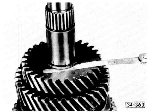
- Measure end play with feeler gauge
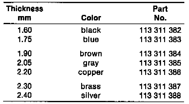
- Adjust by selecting suitable circlip, play should be 0.05-0.20 mm (try to keep lower limit)
- Press pinion needle bearing in gear carrier housing until seated