Engine - Idle Speed Specifications
85VW2Applies To
VANAGON
1985
Group
24
Subject Fuel Injection System
Part Identifier N/A
Key Points Idle speed specifications Throttle valve switch Vacuum hose layout
Heater, crankcase ventilation A148
Number
85-01
May 31, 1985
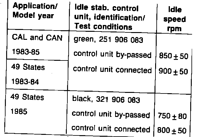
Idle speed, specifications
Note Replacing digital idle stabilization control unit can lower idle speed rpm.. When replacing control unit, always recheck idle speed and adjust as necessary.
Throttle valve switch
Function
With throttle valve closed, switch signals control unit about the following
^ idle injection quantity
^ switching off injection during deceleration
With throttle valve open, switch signals control unit about the following
^ full throttle injection quantity
CAUTION: Do not connect test light to terminals throttle switch unless control unit is disconnected.
Throttle valve switch, checking/adjusting
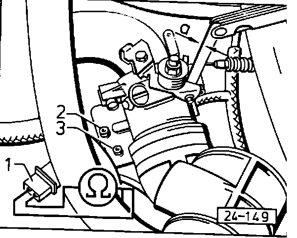
- connect ohmmeter across terminals of unplugged switch connector 1
^ ohmmeter must read 0 Ohms only when throttle lever is at idle stop and full throttle stop
^ check switch-on point of throttle switch as follows
- open throttle valve and slowly close
- measure switch-on point with feeler gauge between idle stop and idle adjusting screw
^ must be 0.05-0.10 mm (0.002-0.004 in) before idle stop (gap a) If measurement NOT OK
- correct by adjusting position of switch. Loosen screw 2 and adjust screw 3
CAUTION: Basic throttle valve adjustment must NOT be changed.
Note
Correct adjustment is important. Following are conditions that are created by improper adjustment
^ gap a too large Engine surges with lean condition
^ gap a too small With cold engine, stalling at full throttle acceleration. With engine warm, no deceleration fuel shut-off
Control unit and wiring, checking
Work sequence
- switch ignition ON
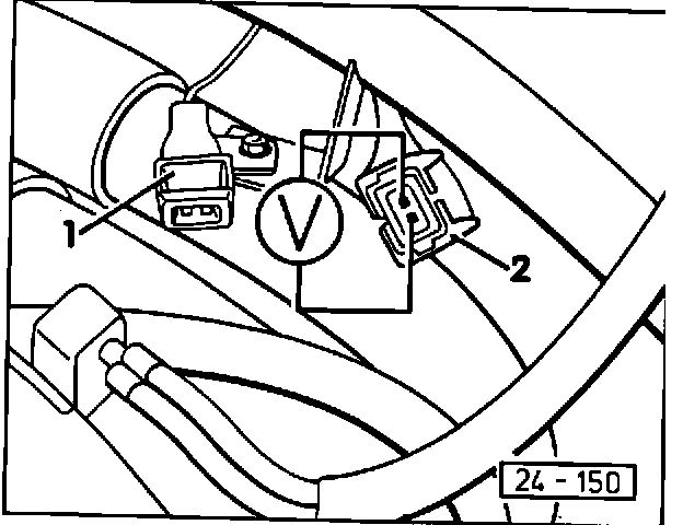
- using voltmeter, check voltage present across terminals of connector 2
^ must be approx. 5V
If voltage reading NOT OK
- check for open circuit in wiring according to current flow diagram
If wiring OK
- replace control unit
Deceleration fuel shut-off, checking
Test conditions
^ temp. sensor II minimum 60~C (140~F) with resistance reading less than 550 Ohms
Work sequence
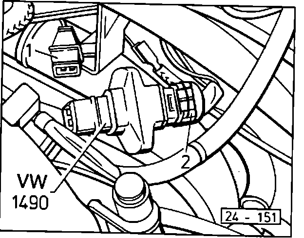
- using end of tool VW 1490, bridge terminals of connector 2
- accelerate engine slightly
^ engine rpm must fluctuate (deceleration fuel shut-off system operates)
If rpm DOES NOT fluctuate
- replace control unit
Full throttle enrichment, checking
Test conditions
^ temp. sensor II minimum 60~C (140~F)
^ CO testor and tachometer connected
- start engine and let idle approx. two minutes
- slowly accelerate engine until 4000 rpm is reached
^ CO must read 0.3 - 1.1% Vol.
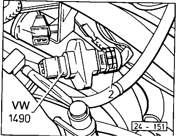
- using end of tool VW 1490, bridge terminals of connector 2
^ CO reading must increase above 1.5% Vol.
If CO readings NOT OK
- replace control unit
Throttle valve switch, removing/installing
Work sequence
- remove throttle body
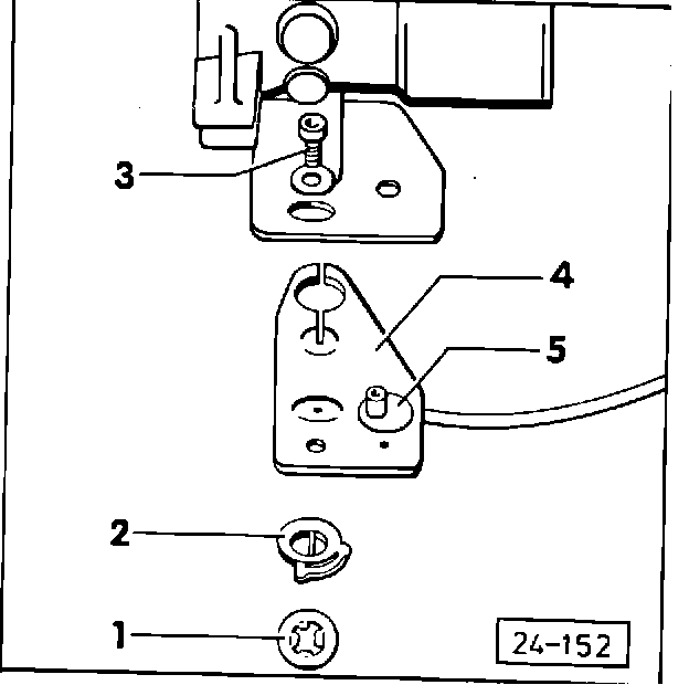
- remove switch 4 following numerical sequence of components 1 through 5
- install components in reverse order
- perform basic adjustment as follows
Throttle valve, basic adjustment
Note
Stop screw is set at factory and should not be moved. If screw position has been altered, check basic adjustment as follows
Work sequence
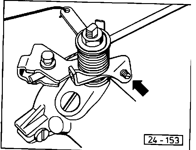
- turn adjusting screw (arrow) out until gap exists between stop and screw
- turn screw in until it touches stop
Note
In order to determine exact point of contact with screw stop, place a thin piece of paper between screw and stop. Slide paper and turn screw at same time until screw pinches paper.
- turn screw clockwise additional 1/2 turn
- check idle speed and CO; adjust if necessary
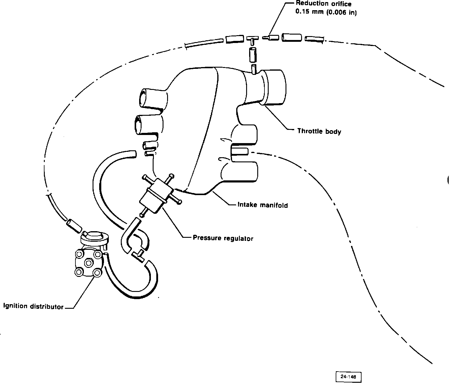
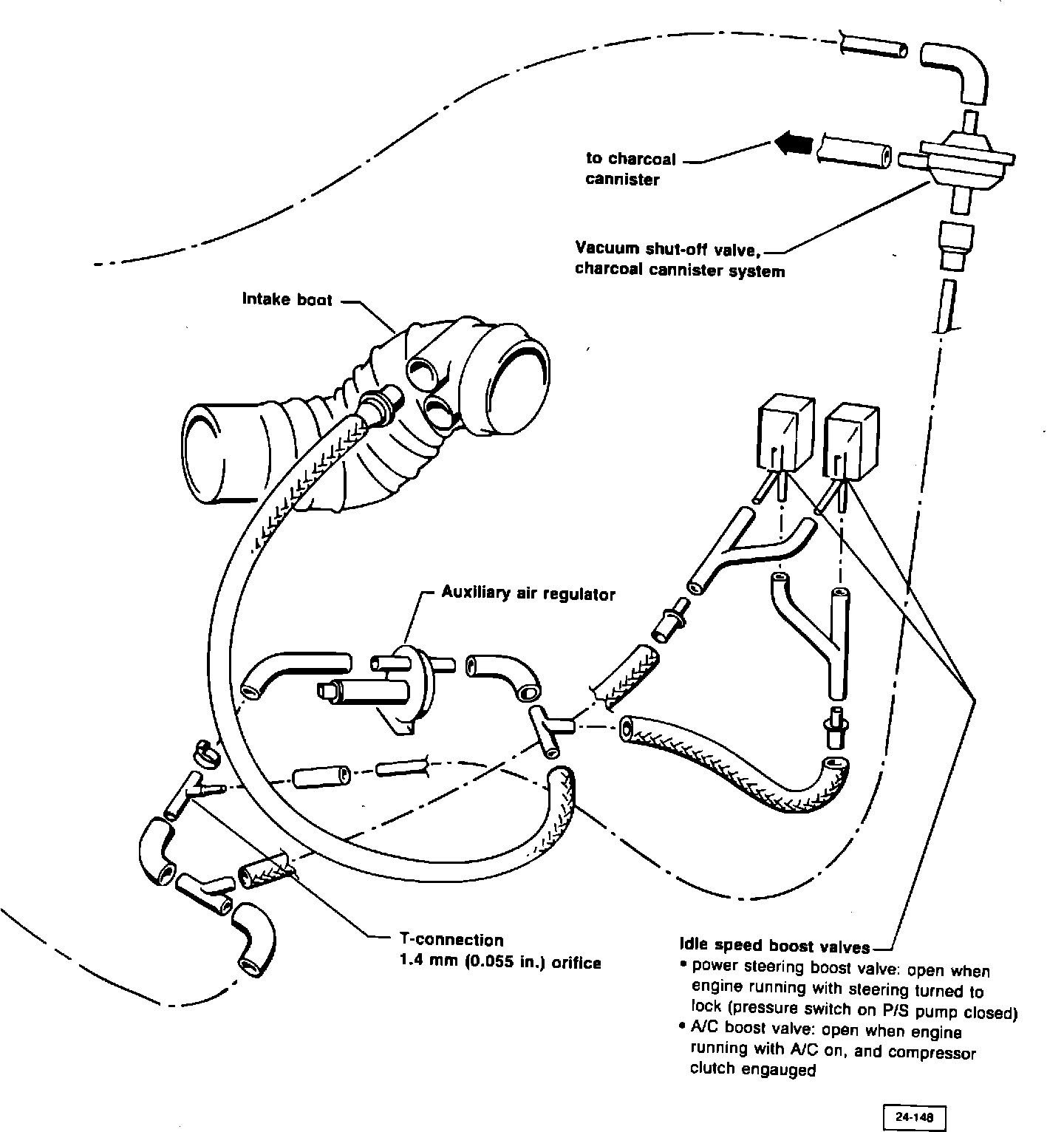
Vacuum hose lay-out
Heater, crankcase ventilation (Canada only)
FIGURE 1 - HEATER 1, WITHOUT RESTRICTOR 2 FOR CANADA ONLY:
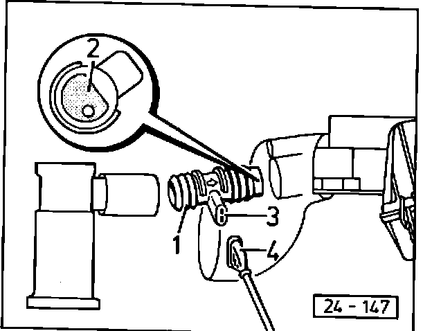
Work sequence
- install with arrow stamped on heater pointing toward vacuum source and electrical connector 3 angled approx. 60~ to right
Checking
- switch ignition ON
- using voltmeter, check voltage across terminals of connector 4
- unplug connector 4 from heater connector 3
^ must be approx. battery voltage
- using ohmmeter, check resistance across terminals of connector 3
^ must be 4-17 Ohms at approx. 25~C (77~F)