Ignition System Testing
Ignition system testing
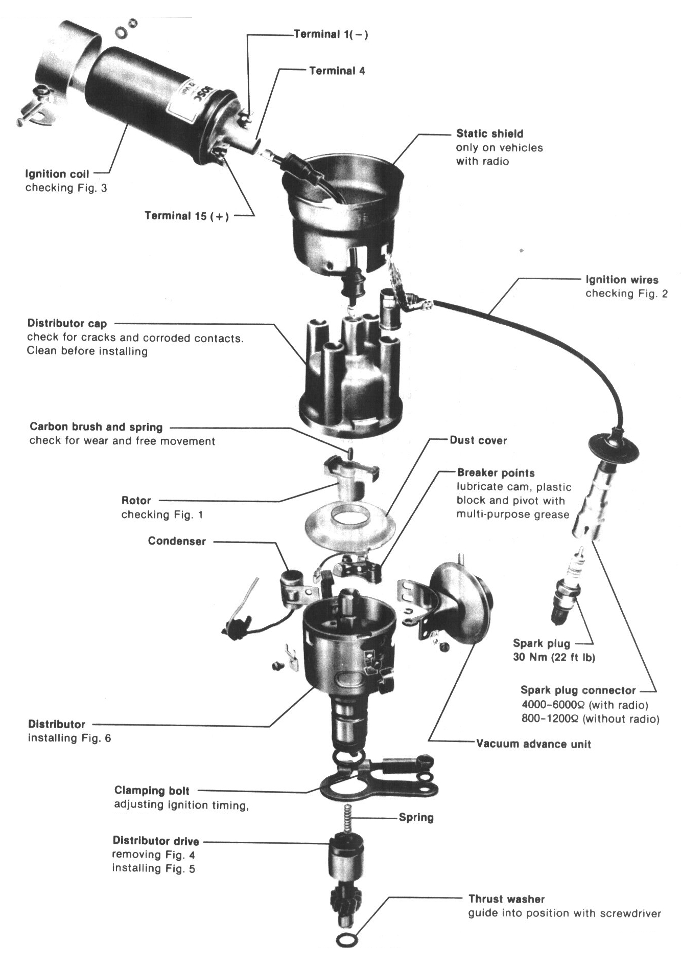
Ignition System Layout:
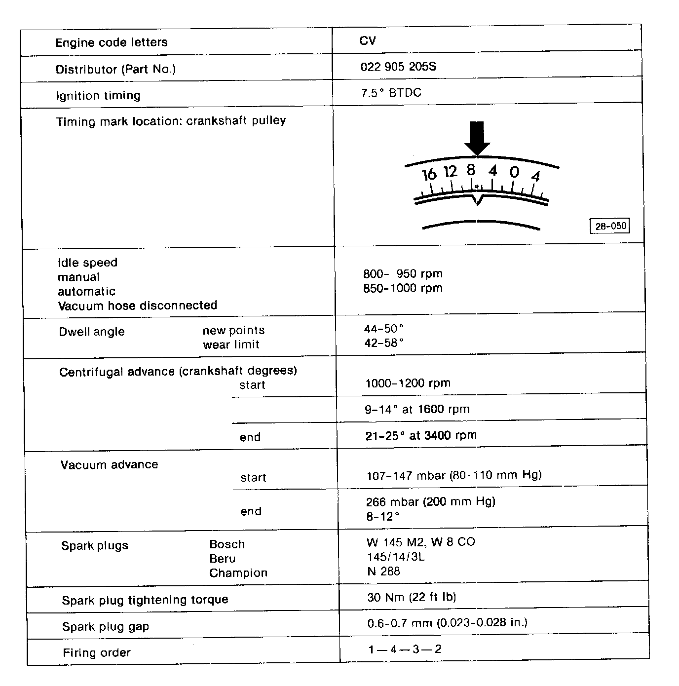
Ignition System Specifications:
Note: A rough idle or misfire during partial load could be caused by ignition sparks jumping from the plug wire connector to the noise suppression shield, or the cylinder head.
- remove and inspect the plug connector for white spots or burn marks
- on those vehicles equipped with a suppressor shield on the distributor cap, it is necessary to remove the shield and check for white spots or burn marks on the distributor cap
If white spots or burn marks are present, replace the damaged components.
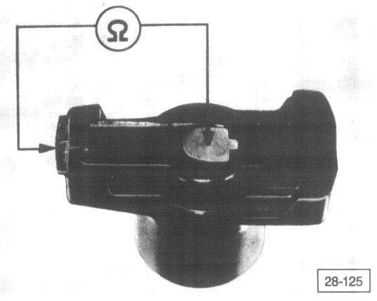
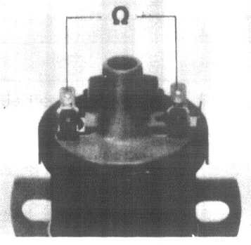
Fig. 1 Rotor, checking
4000 - 6000 ohms
Fig. 2 ignition wires, checking
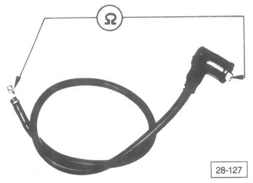
- check wires between distributor and spark plugs (including connectors) for continuity
resistance should not vary greatly between wires
- check wire between ignition coil and distributor (including connector)
resistance should not be greater than 2400 ohms
Fig. 3 ignition coil, checking
- disconnect all wires from coil terminals
- measure resistance between terminals 1 and 15
2.6 - 3.1 ohms
- measure resistance between terminals 1 and 4
6000 - 12000 ohms
Fig. 4 Distributor drive, removing
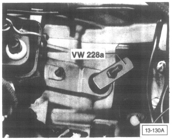
Fig. 5 Distributor drive, installing
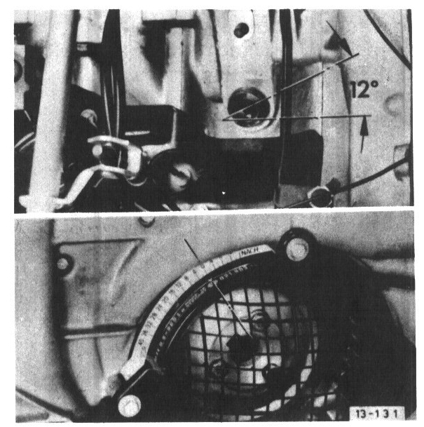
- set crankshaft to TDC on cylinder No.1
- install drive shaft so that offset slot is at an angle of about 12° to engine centerline (small segment to coil side)
Fig. 6 Distributor, installing
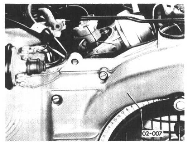
- set crankshaft to TDC on cylinder No 1
- turn rotor until it is pointing to No 1 cylinder mark on edge of housing
- install distributor
- clean distributor cap, check for cracks, signs of tracking and rotor tightness on shaft
- adjust ignition timing