Instrument Panel Removal and Installation: Removal
- Disable air bag system, see DISABLING AIR BAG SYSTEM
.
- Remove floor console front panel, see CENTER CONSOLE BOX REMOVAL AND INSTALLATION
.
- Remove front pillar trim, see TRIM REMOVAL AND INSTALLATION
.
- Remove dash side trim and side sill front scuff, see TRIM REMOVAL AND INSTALLATION
.
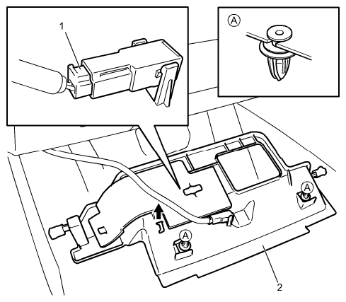
- Remove driver side instrument panel undercover (2), and then disconnect connector (1) while supporting it.
 Courtesy of SUZUKI OF AMERICA CORP.
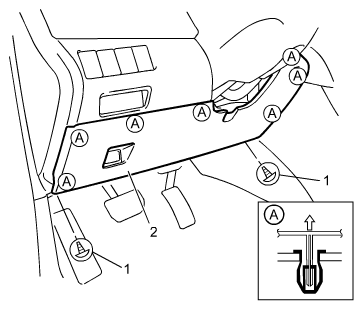
- Remove screws (1) and remove steering column hole cover (2).
 Courtesy of SUZUKI OF AMERICA CORP.
- Remove steering column assembly, see STEERING COLUMN REMOVAL AND INSTALLATION
.
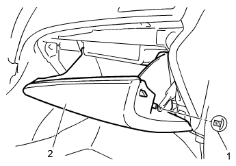
- Remove screws (1) and remove glove box (2).
 Courtesy of SUZUKI OF AMERICA CORP.
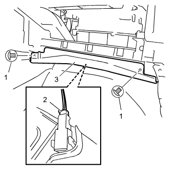
- Remove screws (1) to detach instrument panel undercover (3), and then disconnect floor light connector while supporting it.
 Courtesy of SUZUKI OF AMERICA CORP.
- Remove foot duct, see BLOWER MOTOR REMOVAL AND INSTALLATION
.
- Remove steering support member lower bracket bolts (1) and remove steering support member lower bracket (2).
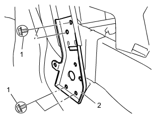 Courtesy of SUZUKI OF AMERICA CORP.
- Disconnect/remove the following parts as shown in figure: connectors (1) to (18), ground connections (19) and inside air temperature sensor aspirator duct (20).
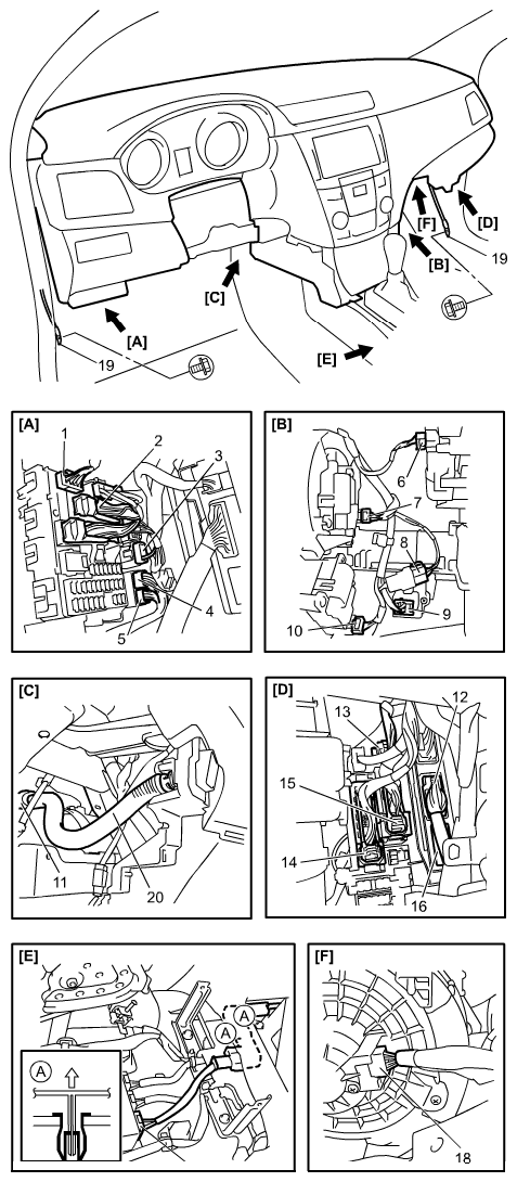 Courtesy of SUZUKI OF AMERICA CORP.
- Remove steering support member bolts (1) and (2).
- Check that there is no harness or ground wire connected between instrument panel and vehicle while slightly raising and supporting instrument panel (3).
- Remove instrument panel, steering support member and instrument panel harness as assembly.
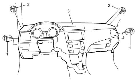 Courtesy of SUZUKI OF AMERICA CORP.