Manual Transmission Assembly Dismounting and Remounting: Dismounting
- Disconnect negative (-) cable of battery.
- Remove transmission shift control lever referring to TRANSMISSION SHIFT CONTROL LEVER REMOVAL AND INSTALLATION .
- Detach engine harness clamps and ground wire harness from transmission front case.
- Remove starting motor fastening bolts (2), transmission fastening bolts (1) and fastening nuts (3).
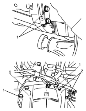 Courtesy of SUZUKI OF AMERICA CORP.
- Disconnect clutch fluid joint from pipe of clutch operating cylinder assembly referring to CLUTCH OPERATING CYLINDER ASSEMBLY REMOVAL AND INSTALLATION
.
- Hoist vehicle.
- Drain oil from transmission and transfer or extension case.
- Remove propeller shafts referring to PROPELLER SHAFT REMOVAL AND INSTALLATION
.
- Remove exhaust No. 2 pipe.
- Remove engine undercover.
- Remove clutch housing lower plates (1).
- Remove transmission fastening nut (2) and bolts (3).
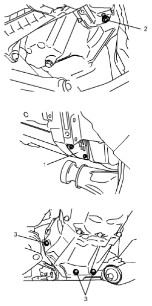 Courtesy of SUZUKI OF AMERICA CORP.
- Disconnect the following couplers and release their harness from clamps.
- Back up light switch
- Transfer shift actuator (if equipped)
- 4L/N switch (if equipped)
- Center differential lock switch (if equipped)
- Apply transmission jack (1) and remove engine rear mounting member (2) taking off its bolts.
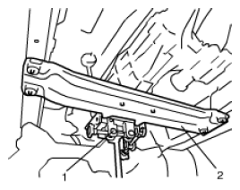 Courtesy of SUZUKI OF AMERICA CORP.
- After removing mounting member, move rearward transmission and transfer or extension case assemblies placed on jack and then lower them.
- Separate gear shift control arm assembly (2) and transfer assembly (3) or extension case from transmission assembly (1).
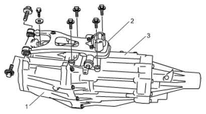 Courtesy of SUZUKI OF AMERICA CORP.