Diagnosis Procedure
DIAGNOSIS PROCEDURE MALFUNCTION A
| Step |
Action |
YES |
NO |
| 1 |
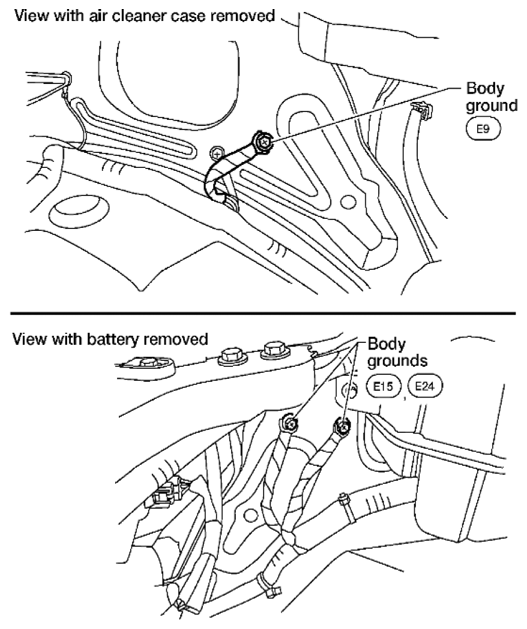
CHECK GROUND CONNECTIONS
- Turn ignition switch OFF.
- Loosen and retighten three ground screws on the body. Refer to
[POWER SUPPLY AND GROUND CIRCUIT CHECK
].
 Courtesy of SUZUKI OF AMERICA CORP. Courtesy of SUZUKI OF AMERICA CORP.
OK or NG |
GO TO 2. |
Repair or replace ground connections. |
| 2 |
CLEAR THE SELF-LEARNING DATA 1) With SDT
- Start engine and warm it up to normal operating temperature.
- Select "SELF-LEARNING CONT" in "Utility" mode with SDT.
- Clear the self-learning control coefficient by touching "CLEAR".
- Run engine for at least 10 minutes at idle speed. Is the 1st trip DTC P0171, P0172, P0174 or P0175 detected? Is it difficult to start engine?
2) Without SDT
- Start engine and warm it up to normal operating temperature.
- Turn ignition switch OFF.
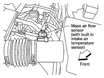
- Disconnect mass air flow sensor harness connector, and restart and run engine for at least 5 seconds at idle speed.
 Courtesy of SUZUKI OF AMERICA CORP. Courtesy of SUZUKI OF AMERICA CORP.
- Stop engine and reconnect mass air flow sensor harness connector.
- Check DTC P0102 is displayed.
- Erase the DTC memory. Refer to EMISSION-RELATED DIAGNOSTIC INFORMATION ITEMS
.
- eck DTC P0000 is displayed.
- Run engine for at least 10 minutes at idle speed. Is the 1st trip DTC P0171, P0172, P0174 or P0175 detected? Is it difficult to start engine?
Yes or No |
Perform trouble diagnosis for DTC P0171, P0174 or P0172, P0175. Refer to DTC P0171, P0174: Fuel Injection System Function or DTC P0172, P0175: Fuel Injection System Function . |
GO TO 3. |
| 3 |
CHECK HO2S2 INPUT SIGNAL CIRCUIT FOR OPEN AND SHORT
- urn ignition switch OFF.
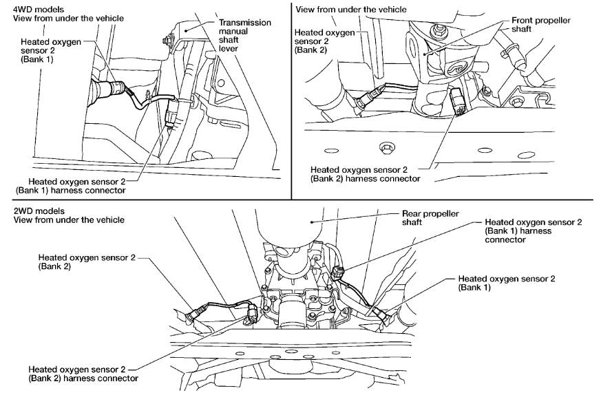
- Disconnect heated oxygen sensor 2 harness connector.
 Courtesy of SUZUKI OF AMERICA CORP. Courtesy of SUZUKI OF AMERICA CORP.
- Disconnect ECM harness connector.
- Check harness continuity between HO2S2 terminal 4 and ECM terminal 78. Refer to Wiring Diagram.
Continuity should exist.
- Also check harness for short to ground and short to power.
OK or NG |
GO TO 4. |
Repair open circuit or short to ground or short to power in harness or connectors. |
| 4 |
CHECK HO2S2 INPUT SIGNAL CIRCUIT FOR OPEN AND SHORT
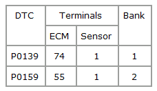
- Check harness continuity between ECM terminal and HO2S2 terminal as follows. Refer to Wiring Diagram.
 Courtesy of SUZUKI OF AMERICA CORP. Courtesy of SUZUKI OF AMERICA CORP.
Continuity should exist.
- Check harness continuity between the following terminals and ground. Refer to Wiring Diagram.
Courtesy of SUZUKI OF AMERICA CORP.
Continuity should not exist.
- Also check harness for short to power.
OK or NG |
GO TO 5. |
Repair open circuit or short to ground or short to power in harness or connectors. |
| 5 |
CHECK HEATED OXYGEN SENSOR 2
Refer to
[P0139, P0159 HO2S2 ].
OK or NG |
GO TO 6. |
Replace malfunctioning heated oxygen sensor 2. |
| 6 |
CHECK INTERMITTENT INCIDENT
Refer to
[SERVICE INFORMATION FOR ELECTRICAL INCIDENT: INTERMITTENT INCIDENT
] |
INSPECTION END |
|