| 1 |
CHECK ENGINE START
Turn ignition switch OFF, and restart engine.
Is engine running?
Yes or No |
GO TO 2. |
GO TO 3. |
| 2 |
CHECK OVERALL FUNCTION
With SDT
- Perform "POWER BALANCE" in "Active test" mode with SDT.
- Make sure that each circuit produce a momentary engine speed drop.
OK or NG |
INSPECTION END |
GO TO 10. |
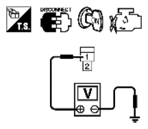
| 3 |
CHECK OVERALL FUNCTION
Without SDT
- Let engine idle.
- Read the voltage signal between ECM terminals 61, 62, 80, 81 and ground with an oscilloscope.
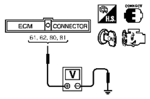 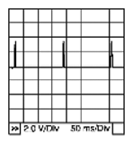 Courtesy of SUZUKI OF AMERICA CORP.SUZUKI OF AMERICA CORP. Courtesy of SUZUKI OF AMERICA CORP.SUZUKI OF AMERICA CORP.
- 3. Verify that the oscilloscope screen shows the signal wave as shown below.
NOTE:
The pulse cycle changes depending on RPM at idle.
Courtesy of SUZUKI OF AMERICA CORP.SUZUKI OF AMERICA CORP.
OK or NG |
INSPECTION END |
GO TO 10. |
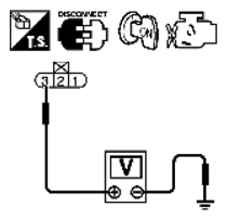
| 4 |
CHECK IGNITION COIL POWER SUPPLY CIRCUIT-I
- Turn ignition switch OFF, wait at least 10 seconds and then turn ON.
- Check voltage between ECM terminals 119, 120 and ground with SDT or tester.
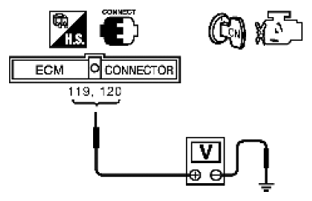 Courtesy of SUZUKI OF AMERICA CORP. Courtesy of SUZUKI OF AMERICA CORP.
Voltage: Battery voltage
OK or NG |
GO TO 5. |
Go to POWER SUPPLY AND GROUND CIRCUIT CHECK
. |
| 5 |
CHECK IGNITION COIL POWER SUPPLY CIRCUIT-II
- Turn ignition switch OFF.
- Disconnect condenser-1 harness connector.
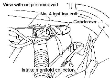  Courtesy of SUZUKI OF AMERICA CORP.SUZUKI OF AMERICA CORP. Courtesy of SUZUKI OF AMERICA CORP.SUZUKI OF AMERICA CORP.
- 3. Turn ignition switch ON.
- 4. Check voltage between condenser-1 terminal 1 and ground with SDT or tester.
Courtesy of SUZUKI OF AMERICA CORP.SUZUKI OF AMERICA CORP.
Voltage: Battery voltage
OK or NG |
GO TO 8. |
GO TO 6. |
| 6 |
CHECK IGNITION COIL POWER SUPPLY CIRCUIT-III
- Turn ignition switch OFF.
- Disconnect IPDM E/R harness connector E119.
- Check harness continuity between IPDM E/R terminal 3 and condenser-1 terminal 1. Refer to WIRING DIAGRAM
.
Continuity should exist.
- Also check harness for short to ground and short to power.
OK or NG |
GO TO 15. |
GO TO 7. |
| 7 |
DETECT MALFUNCTIONING PART
Check the following.
- Harness connectors E2, F32
- Harness for open or short between condenser-1 and IPDM E/R
|
Repair open circuit, short to ground or short to power in harness or connectors. |
|
| 8 |
CHECK CONDENSER-1 GROUND CIRCUIT FOR OPEN AND SHORT
- Turn ignition switch OFF.
- Check harness continuity between condenser-1 terminal 2 and ground. Refer to WIRING DIAGRAM
.
Continuity should exist.
- Also check harness for short to power.
OK or NG |
GO TO 9. |
Repair open circuit or short to power in harness or connectors. |
| 9 |
CHECK CONDENSER-1
Refer to
[IGNITION SIGNAL CIRCUIT CHECK ].
OK or NG |
GO TO 10. |
Replace condenser-1. |
| 10 |
CHECK IGNITION COIL POWER SUPPLY CIRCUIT-IV
- Turn ignition switch OFF.
- Reconnect all harness connectors disconnected.
- Disconnect ignition coil harness connector.
  Courtesy of SUZUKI OF AMERICA CORP.SUZUKI OF AMERICA CORP. Courtesy of SUZUKI OF AMERICA CORP.SUZUKI OF AMERICA CORP.
- 4. Turn ignition switch ON.
- 5. Check voltage between ignition coil terminal 3 and ground with SDT or tester.
Courtesy of SUZUKI OF AMERICA CORP.SUZUKI OF AMERICA CORP.
Voltage: Battery voltage
OK or NG |
GO TO 12. |
GO TO 11. |
| 11 |
DETECT MALFUNCTIONING PART
Check the following.
- Harness connector E2, F32
- Harness for open or short between ignition coil and IPDM E/R.
|
Repair open circuit, short to ground or short to power in harness or connectors. |
|
| 12 |
CHECK IGNITION COIL GROUND CIRCUIT FOR OPEN AND SHORT
- Turn ignition switch OFF.
- Check harness continuity between ignition coil terminal 2 and ground. Refer to WIRING DIAGRAM
.
Continuity should exist.
- Also check harness for short to power.
OK or NG |
GO TO 13. |
Repair open circuit or short to power in harness or connectors. |
| 13 |
CHECK IGNITION COIL OUTPUT SIGNAL CIRCUIT FOR OPEN AND SHORT
- Disconnect ECM harness connector.
- Check harness continuity between ECM terminals 61, 62, 80, 81 and ignition coil terminal 1. Refer to WIRING DIAGRAM
.
Continuity should exist.
- Also check harness for short to ground and short to power.
OK or NG |
GO TO 14. |
Repair open circuit, short to ground or short to power in harness or connectors. |
| 14 |
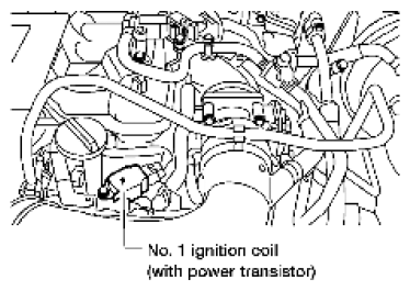
CHECK IGNITION COIL WITH POWER TRANSISTOR
Refer to
[Component Inspection ].
OK or NG |
GO TO 15. |
Replace ignition coil with power transistor. |
| 15 |
CHECK INTERMITTENT INCIDENT
Refer to
[SERVICE INFORMATION FOR ELECTRICAL INCIDENT: INTERMITTENT INCIDENT
] |
INSPECTION END |
|