OBD System Description - Catalyst Monitor
OBD System Description - Catalyst Monitor
System Description / Monitoring Procedure
Exhaust oxygen concentration at the upstream and the downstream of WU-TWC is detected from A/F sensor and HO2S respectively and accordingly ECM controls the closed-loop which then controls the fuel injection volume. If the WU-TWC is in good condition while the above controls are in operation, the output voltage of HO2S is maintained at the specified level. If the WU-TWC becomes deteriorated, the exhaust gas which passed WU-TWC passes HO2S at the exhaust oxygen concentration similar to that of the upstream of WU-TWC without being oxygenated or converted, even when the above controls are in operation. In this way, waveforms of the A/F sensor and HO2S output voltage become alike and the ECM judges the deterioration of WU-TWC by comparing waveforms of A/F sensor and HO2S.
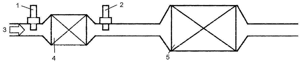
Catalyst System Layout
The system has A/F sensor and HO2S located upstream and downstream of WU-TWC as shown in figure.
WU-TWC, A/F sensor and HO2S layout
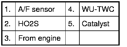
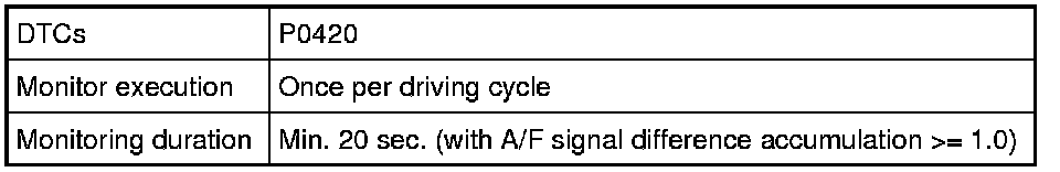
DTC Description / Detecting Condition / Confirmation Procedure
P0420
Refer to P0420 DTC P0420.
Catalyst Monitor
Operation
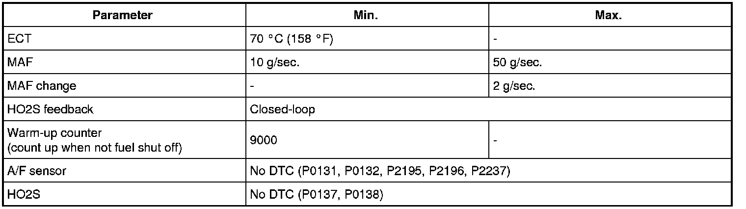
Enabled conditions
Typical malfunction thresholds

MODE $06 Data
