Radiator Cooling Fan Control System Check
Radiator Cooling Fan Control System Check
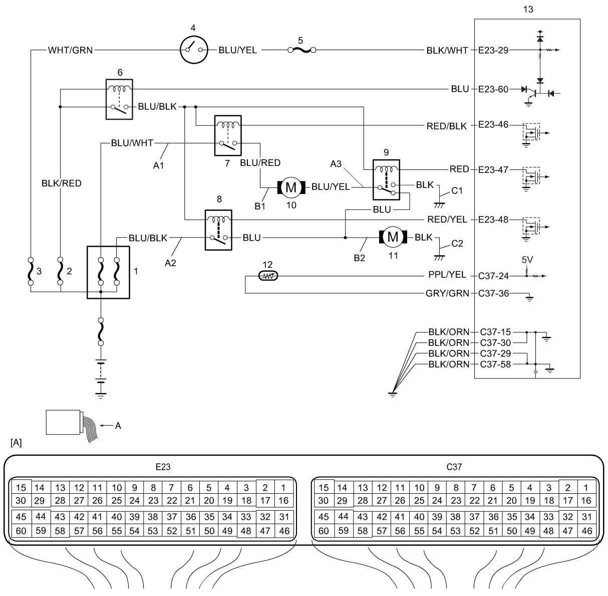
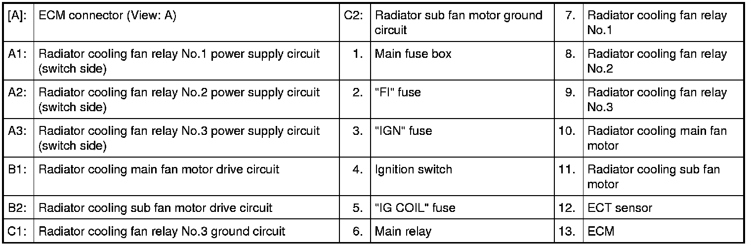
Wiring Diagram
Troubleshooting
WARNING:
The radiator cooling fan can come on whenever the ignition switch is in the "ON" position. This electric fan starts automatically anytime the ECT sensor senses a coolant temperature higher than a predetermined level even when the engine is not running.
When the ignition switch is in the ON position, be sure to keep hands, tools, clothing, and other items away from the radiator cooling fan and drive belt.
NOTE:
- For details about engine cooling fan operation, refer to Description and Operation Cooling Fan Description.
- Before beginning troubleshooting, be sure to read Precautions for ECM Circuit Inspection Precautions for ECM Circuit Inspection.
- When measuring circuit voltage, resistance and/or pulse signal of ECM, connect the special tool between ECM and ECM connectors. Pinout Values and Diagnostic Parameters
1. DTC Check
Turn OFF ignition switch and connect SUZUKI scan tool to data link connector (DLC).
Turn ignition switch to ON position and check DTC.
Is there DTC(s)?
YES
Go to applicable DTC flow and recheck.
NO
Go to Step 2.
2. Radiator cooling fan low mode control check
Check radiator cooling fan control for low mode. Radiator Cooling Fan Assembly On-Vehicle Inspection
Is it in good condition?
YES
Go to Step 3.
NO
Go to Step 6.
3. Radiator cooling fan mid and high mode control check
Check radiator cooling fan control for mid and high mode. Radiator Cooling Fan Assembly On-Vehicle Inspection
Is it in good condition?
YES
Radiator cooling fan control system is in good condition.
NO
Go to Step 4.
4. Radiator cooling fan relay No.2 power supply circuit (switch side) check
Turn OFF ignition switch and remove radiator cooling fan relay No.2 from relay box.
Check for proper connection to radiator cooling fan relay No.2 at each terminal.
If OK, measure voltage between radiator cooling fan relay No.2 power supply circuit (A2) and vehicle body ground.
Is it 10 - 14 V?
YES
Go to Step 5.
NO
Repair or replace radiator cooling fan relay No.2 power supply circuit (switch side).
5. Radiator cooling fan relay No.3 ground circuit check
Turn OFF ignition switch and remove radiator cooling fan relay No.3 from relay box.
Check for proper connection to radiator cooling fan relay No.3 at each terminal.
If OK, measure resistance between radiator cooling fan relay No.3 ground circuit (C1) and vehicle body ground.
Is resistance 3 or less?
YES
Go to Step 6.
NO
Repair or replace radiator cooling fan relay No.3 ground circuit.
6. Radiator cooling fan relay No.1 power supply circuit (switch side) check
Turn OFF ignition switch and remove radiator cooling fan relay No.1 from relay box.
Check for proper connection to radiator cooling fan relay No.1 at each terminal.
If OK, measure voltage between radiator cooling fan relay No.1 power supply circuit (A1) and vehicle body ground.
Is it 10 - 14 V?
YES
Go to Step 7.
NO
Repair or replace radiator cooling fan relay No.1 power supply circuit (switch side).
7. Radiator cooling fan relay No.1, No.2 and No.3 check
Check radiator cooling fan relay No.1, No.2 and No.3. Testing and Inspection
Is it in good condition?
YES
Go to Step 8.
NO
Replace faulty radiator cooling fan relay.
8. Main fan motor drive circuit check
Turin OFF ignition switch and disconnect main fan motor connector.
Check for proper connection to main fan motor at each terminal.
If OK, check that main fan motor drive circuit (B1) is in the following conditions.
Wiring harness resistance of main fan motor drive circuit is less than 3 or less.
Insulation resistance between main fan drive circuit and vehicle body ground is infinity.
Circuit voltage of main fan motor drive circuit is 0 - 1 V with ignition switch in ON position.
Are they in good condition?
YES
Go to Step 9.
NO
Repair or replace main fan motor drive circuit.
9. Radiator cooling fan relay No.3 power supply circuit (switch side) check
Check that radiator cooling fan relay No.3 power supply circuit (switch side) (A3) is in the following conditions.
Wiring harness resistance of radiator cooling fan relay No.3 power supply circuit (switch side) is 3 or less.
Insulation resistance between radiator cooling fan relay No.3 power supply circuit (switch side) and vehicle body ground is infinity.
Circuit voltage of radiator cooling fan relay No.3 power supply circuit (switch side) is 0 - 1 V with ignition switch in ON position.
Is it in good condition?
YES
Go to Step 10.
NO
Repair or replace radiator cooling fan relay No.3 power supply circuit (switch side).
10. Sub fan motor drive circuit check
Turn OFF ignition switch and disconnect sub fan motor connector.
Check for proper connection to sub fan motor at each terminal.
If OK, check that sub fan motor drive circuit (B2) is in the following conditions.
Wiring harness resistance of sub fan motor drive circuit is 3 or less.
Insulation resistance between sub fan drive circuit and vehicle body ground is infinity.
Circuit voltage of sub fan motor drive circuit is 0 - 1 V with ignition switch in ON position.
Is it in good condition?
YES
Go to Step 11.
NO
Repair or replace sub fan motor drive circuit.
11. Sub fan motor ground circuit check
Measure resistance between sub fan motor ground circuit (C2) and vehicle body ground.
Is resistance 3 or less?
YES
Go to Step 12.
NO
Repair or replace sub fan motor ground circuit.
12. Main fan motor and sub fan motor check
Check main fan motor and sub fan motor. Radiator Cooling Fan Assembly On-Vehicle Inspection
Is it in good condition?
YES
Substitute a known-good ECM and recheck.
NO
Replace main fan motor or sub fan motor. Removal and Replacement