P2196
DTC P0131 / P0132 / P0134 / P2195 / P2196 / P2237
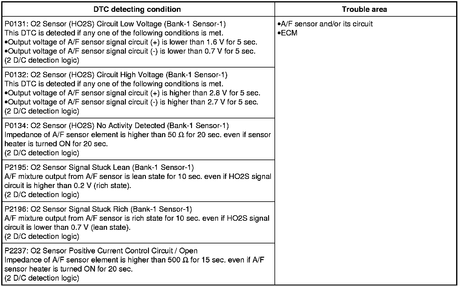
DTC Detecting Condition and Trouble Area
Wiring Diagram
Refer to P0031 DTC P0031 / P0032.
DTC Confirmation Procedure
NOTE:
If DTCs other than aimed DTC are previously detected in DTC confirmation procedure, be sure to troubleshoot DTC previously detected.
P0131 / P0132:
1) Start engine and warm up to normal operating temperature.
2) Run engine at idle speed for 1 min.
P0134 / P2237:
3) Start engine and warm up to normal operating temperature.
4) Run engine at idle speed for 2 min.
P2195 / P2196:
WARNING:
If you do not select a suitable route and take proper precautions when performing a road test, an accident can occur.
- Select a level road with no traffic to minimize the risk of accident.
- Perform the test extremely carefully.
- Perform the road test using 2 persons, a driver and an assistant.
NOTE:
Check to make sure that the following condition is satisfied when using this procedure.
- BARO > 75 kPa (0.8 kgf/cm2, 10.8 psi, 0.75 bar)
5) Start engine and warm up to normal operating temperature.
6) Drive vehicle at 50 - 60 km/h (31 - 37 mile/h) (engine speed: 1,500 - 3,000 rpm) for 3 min. (Keep throttle valve opening constantly in this step.)
DTC Troubleshooting
1. Was "Engine and Emission Control System Check" performed?
YES
Go to Step 2.
NO
Go to Engine and Emission Control System Check Engine and Emission Control System Check.
2. DTC check
Is there any DTC(s) other than P0131, P0132, P0134, P2195, P2196 and P2237?
YES
Go to troubleshooting for applicable DTC.
NO
Go to Step 3.
3. A/F sensor signal circuit check
Turn OFF ignition switch and disconnect connectors from A/F sensor and ECM.
Check for proper terminal connection to A/F sensor and ECM connectors.
Check that A/F sensor signal circuits (A3 - A4) are as follows.
Wiring harness resistance of each A/F sensor signal circuit is less than 3.
Insulation resistance between each A/F sensor signal circuit and vehicle body ground is infinity.
Insulation resistance of wire harness is infinity between each A/F sensor signal terminal and each terminal at A/F sensor connector.
Circuit voltage of each A/F sensor signal circuit is 0 - 1 V with ignition switch in ON position.
Are they in good condition?
YES
Go to Step 4.
NO
Repair or replace defective wire harness.
4. DTC recheck
Replace A/F sensor. Service and Repair
Perform DTC confirmation procedure and check DTC.
Is DTC P0131, P0132, P0134, P2195, P2196 and P2237 still detected?
YES
Substitute a known-good ECM and recheck.
NO
End.