P0533
DTC P0532 / P0533
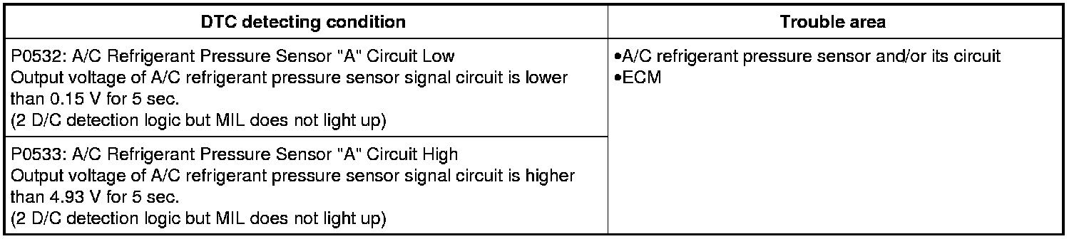
DTC Detecting Condition and Trouble Area
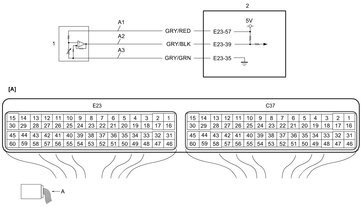
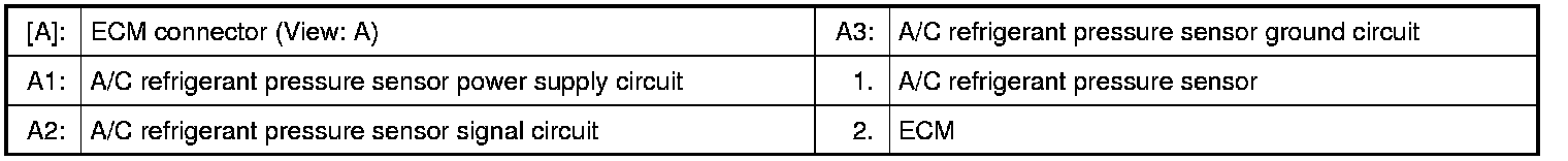
Wiring Diagram
DTC Confirmation Procedure
1) Start engine and operate A/C for 10 sec.
DTC Troubleshooting
1. Was "Engine and Emission Control System Check" performed?
YES
Go to Step 2.
NO
Go to Engine and Emission Control System Check Engine and Emission Control System Check.
2. A/C refrigerant pressure sensor power supply circuit check
Turn OFF ignition switch and disconnect connector from A/C refrigerant pressure sensor.
Check for proper terminal connection to A/C refrigerant pressure sensor connector.
If connections are OK, turn ignition switch to ON position.
Check that voltage between A/C refrigerant pressure sensor power supply circuit (A1) and ground circuit (A3) is 5 V.
Is it in good condition?
YES
Go to Step 5.
NO
Go to Step 3.
3. A/C refrigerant pressure sensor power supply circuit check
Check that voltage between A/C refrigerant pressure sensor power supply circuit (A1) and vehicle body ground is 5 V.
Is it in good condition?
YES
Repair or replace defective wire harness.
If this DTC is detected again, substitute a known-good ECM and recheck.
NO
Go to Step 4.
4. A/C refrigerant pressure sensor power supply circuit check
Turn OFF ignition switch and disconnect connectors from ECM.
Check for proper terminal connection to ECM connectors.
If connections are OK, check that A/C refrigerant pressure sensor power supply circuit (A1) is as follows.
Wiring harness resistance of A/C refrigerant pressure sensor power supply circuit is less than 3.
Insulation resistance of A/C refrigerant pressure sensor power supply circuit is infinity between A/C refrigerant pressure sensor and vehicle body ground.
Insulation resistance of wire harness is infinity between A/C refrigerant pressure sensor power supply circuit terminal and each terminal at A/C refrigerant pressure sensor connector.
Circuit voltage of A/C refrigerant pressure sensor power supply circuit is 0 - 1 V with ignition switch in ON position.
Is it in good condition?
YES
Substitute a known-good ECM and recheck.
NO
Repair or replace defective wire harness.
5. A/C refrigerant pressure sensor signal circuit check
Turn OFF ignition switch and disconnect connectors from ECM.
Check for proper terminal connection to ECM connectors.
If connections are OK, check that A/C refrigerant pressure sensor signal circuit (A2) is as follows.
Wiring harness resistance of A/C refrigerant pressure sensor signal circuit is less than 3.
Insulation resistance of A/C refrigerant pressure sensor signal circuit is infinity between A/C refrigerant pressure sensor and vehicle body ground.
Insulation resistance of wire harness is infinity between A/C refrigerant pressure sensor signal circuit terminal and each terminal at A/C refrigerant pressure sensor connector.
Circuit voltage of A/C refrigerant pressure sensor signal circuit is 0 - 1 V with ignition switch in ON position.
Is it in good condition?
YES
Go to Step 6.
NO
Repair or replace defective wire harness.
6. A/C refrigerant pressure sensor check
Check A/C refrigerant pressure sensor. A/C Refrigerant Pressure Sensor and its Circuit Inspection
Is it in good condition?
YES
Substitute a known-good ECM and recheck.
NO
Replace A/C refrigerant pressure sensor.