| 1 |
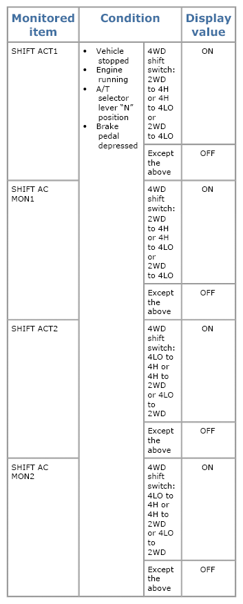
CHECK ACTUATOR MOTOR SIGNAL
- With SDT
- Start engine.
- Select "Data list" mode for "4WD" with SDT.
- Read out the value of "SHIFT ACT1", "SHIFT AC MON1", "SHIFT ACT2", "SHIFT AC MON2".
   Courtesy of SUZUKI OF AMERICA CORP.SUZUKI OF AMERICA CORP.SUZUKI OF AMERICA CORP. Courtesy of SUZUKI OF AMERICA CORP.SUZUKI OF AMERICA CORP.SUZUKI OF AMERICA CORP.
- 2)
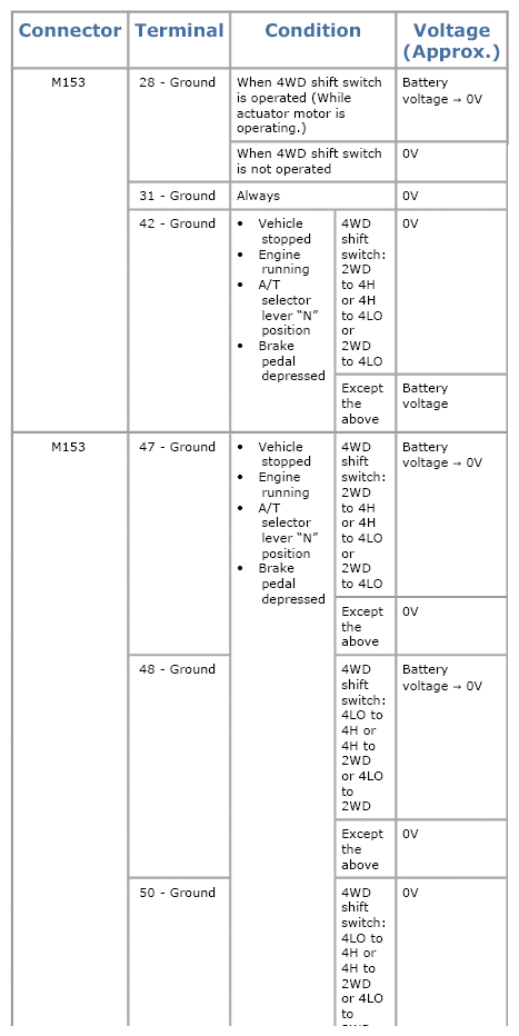
Without SDT
- Start engine.
- Depress brake pedal and stop vehicle.
- Set A/T selector lever to "N" position.
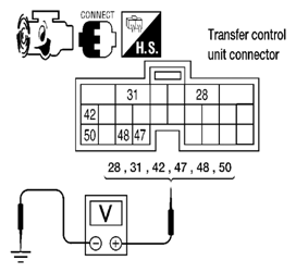
- Check voltage between transfer control unit harness connector terminal and ground.
Courtesy of SUZUKI OF AMERICA CORP.SUZUKI OF AMERICA CORP.SUZUKI OF AMERICA CORP.
Courtesy of SUZUKI OF AMERICA CORP.SUZUKI OF AMERICA CORP.SUZUKI OF AMERICA CORP.
Are the inspection results normal? |
GO TO 9. |
GO TO 2. |
| 2 |
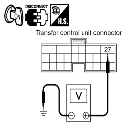
CHECK ACTUATOR MOTOR POWER SUPPLY CIRCUIT
- Turn ignition switch "OFF". (Stay for at least 5 seconds.)
- Disconnect transfer control unit harness connector.
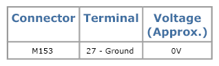
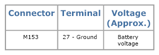
- Check voltage between transfer control unit harness connector terminal 27 and ground.
    Courtesy of SUZUKI OF AMERICA CORP.SUZUKI OF AMERICA CORP.SUZUKI OF AMERICA CORP.SUZUKI OF AMERICA CORP. Courtesy of SUZUKI OF AMERICA CORP.SUZUKI OF AMERICA CORP.SUZUKI OF AMERICA CORP.SUZUKI OF AMERICA CORP.
Courtesy of SUZUKI OF AMERICA CORP.SUZUKI OF AMERICA CORP.SUZUKI OF AMERICA CORP.SUZUKI OF AMERICA CORP.
- 4. Turn ignition switch "ON".
Courtesy of SUZUKI OF AMERICA CORP.SUZUKI OF AMERICA CORP.SUZUKI OF AMERICA CORP.SUZUKI OF AMERICA CORP.
- 5. Check voltage between transfer control unit harness connector terminal 27 and ground.
Courtesy of SUZUKI OF AMERICA CORP.SUZUKI OF AMERICA CORP.SUZUKI OF AMERICA CORP.SUZUKI OF AMERICA CORP.
Are the inspection results normal? |
GO TO 3. |
- Check harness for short or open between transfer control unit harness connector M153 terminal 27 and transfer shut off relay 2 harness connector E157 terminal 5 and 10A fuse (No. 57, located in the fuse and relay block). If any items are damaged, repair or replace damaged parts.
- Perform trouble diagnosis for power supply circuit. Refer to
[P1801, P1811 POWER SUPPLY CIRCUIT FOR TRANSFER CONTROL UNIT ].
|
| 3 |
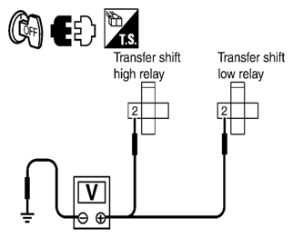
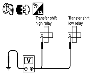
CHECK TRANSFER RELAY POWER SUPPLY CIRCUIT
- Turn ignition switch "OFF". (Stay for at least 5 seconds.)
- Remove transfer shift high relay and transfer shift low relay. Refer to
[4WD SYSTEM: COMPONENT PARTS LOCATION ].
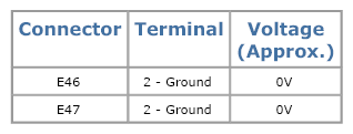
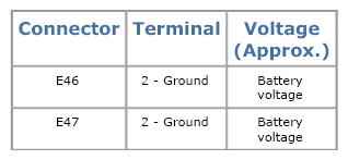
- Check voltage between transfer control unit harness connector terminal and ground.
    Courtesy of SUZUKI OF AMERICA CORP.SUZUKI OF AMERICA CORP.SUZUKI OF AMERICA CORP.SUZUKI OF AMERICA CORP. Courtesy of SUZUKI OF AMERICA CORP.SUZUKI OF AMERICA CORP.SUZUKI OF AMERICA CORP.SUZUKI OF AMERICA CORP.
Courtesy of SUZUKI OF AMERICA CORP.SUZUKI OF AMERICA CORP.SUZUKI OF AMERICA CORP.SUZUKI OF AMERICA CORP.
- 4. Turn ignition switch "ON". (Do not start engine.)
Courtesy of SUZUKI OF AMERICA CORP.SUZUKI OF AMERICA CORP.SUZUKI OF AMERICA CORP.SUZUKI OF AMERICA CORP.
- 5. Check voltage between transfer control unit harness connector terminal and ground.
Courtesy of SUZUKI OF AMERICA CORP.SUZUKI OF AMERICA CORP.SUZUKI OF AMERICA CORP.SUZUKI OF AMERICA CORP.
Are the inspection results normal? |
GO TO 4. |
Check the following. If any items are damaged, repair or replace damaged parts.
- Harness for short or open between transfer control unit harness connector terminal 27 and transfer shift high relay harness connector E46 terminal 2.
- Harness for short or open between transfer control unit harness connector terminal 27 and transfer shift low relay harness connector terminal E47 terminal 2.
|
| 4 |
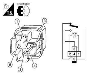
CHECK TRANSFER RELAY
- Turn ignition switch "OFF". (Stay for at least 5 seconds.)
- Remove transfer shift high relay and transfer shift low relay.
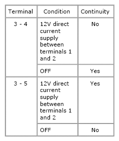
- Apply 12V direct current between transfer shift high and low relay terminals 1 and 2.
  Courtesy of SUZUKI OF AMERICA CORP.SUZUKI OF AMERICA CORP. Courtesy of SUZUKI OF AMERICA CORP.SUZUKI OF AMERICA CORP.
- 4. Check continuity between relay terminals 3 and 4, 3 and 5.
Courtesy of SUZUKI OF AMERICA CORP.SUZUKI OF AMERICA CORP.
Are the inspection results normal? |
GO TO 5. |
Replace the transfer shift high or low relay. |
| 5 |
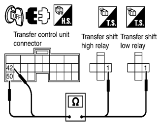
CHECK (1): HARNESS BETWEEN TRANSFER CONTROL UNIT AND TRANSFER SHIFT RELAY
- Turn ignition switch "OFF". (Stay for at least 5 seconds.)
- Disconnect transfer control unit harness connector.
- Remove transfer shift high relay and transfer shift low relay.
- Check continuity between the following terminals.
 Courtesy of SUZUKI OF AMERICA CORP. Courtesy of SUZUKI OF AMERICA CORP.
Is there continuity? |
GO TO 6. |
Repair or replace damaged parts. |
| 6 |
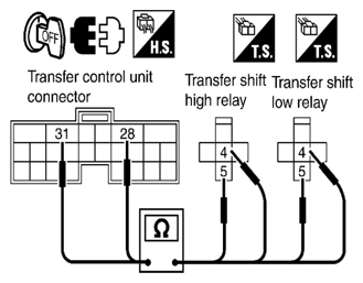
CHECK (2): HARNESS BETWEEN TRANSFER CONTROL UNIT AND TRANSFER SHIFT RELAY
- Turn ignition switch "OFF". (Stay for at least 5 seconds.)
- Disconnect transfer control unit harness connector.
- Remove transfer shift high relay and transfer shift low relay.
- Check continuity between the following terminals.
 Courtesy of SUZUKI OF AMERICA CORP. Courtesy of SUZUKI OF AMERICA CORP.
Is there continuity? |
GO TO 7. |
Repair or replace damaged parts. |
| 7 |
CHECK ACTUATOR MOTOR OPERATION CIRCUIT
- Turn ignition switch "OFF". (Stay for at least 5 seconds.)
- Disconnect transfer control unit harness connector and the transfer control device (actuator motor) harness connector.
- Check continuity between the following terminals.
- Transfer control unit harness connector M153 terminal 47 and transfer control device (actuator motor) harness connector F58 terminal 23.
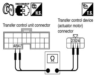  Courtesy of SUZUKI OF AMERICA CORP.SUZUKI OF AMERICA CORP. Courtesy of SUZUKI OF AMERICA CORP.SUZUKI OF AMERICA CORP.
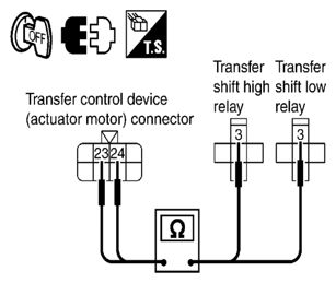
- Transfer control unit harness connector M153 terminal 48 and transfer control device (actuator motor) harness connector F58 terminal 24.
- Transfer control device (actuator motor) harness connector F58 terminal 24 and transfer shift high relay harness connector E46 terminal 3.
Courtesy of SUZUKI OF AMERICA CORP.SUZUKI OF AMERICA CORP.
Is there continuity? |
GO TO 8. |
Repair or replace damaged parts. |
| 8 |
CHECK ACTUATOR MOTOR
- Remove transfer control device. Refer to
[TRANSFER CONTROL DEVICE: REMOVAL AND INSTALLATION ].
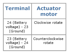
- Check operation by applying battery voltage to transfer control device (actuator motor) terminals 23 and 24.
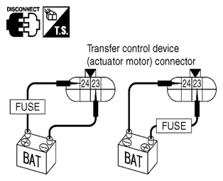  Courtesy of SUZUKI OF AMERICA CORP.SUZUKI OF AMERICA CORP. Courtesy of SUZUKI OF AMERICA CORP.SUZUKI OF AMERICA CORP.
CAUTION:
Be careful not to overheat the harness.
Courtesy of SUZUKI OF AMERICA CORP.SUZUKI OF AMERICA CORP.
Does actuator motor rotate? |
GO TO 9. |
Replace transfer control device (actuator motor). |
| 9 |
CHECK TRANSFER CONTROL UNIT
Check transfer control unit input/output signal. Refer to
[TRANSFER CONTROL UNIT: REFERENCE VALUE ].
Are the inspection results normal? |
GO TO 10. |
Check transfer control unit pin terminals for damage or loose connection with harness connector. If any items are damaged, repair or replace damaged parts. |
| 10 |
CHECK DTC
Perform "DTC check", after driving a vehicle for a while.
Is DTC P1817 displayed? |
Replace transfer control unit. Refer to
[TRANSFER CONTROL UNIT: REMOVAL AND INSTALLATION ]. |
Inspection End. |