Inspection of Power Seat Control System and Its Circuits (If Equipped)
Inspection Of Power Seat Control System And Its Circuits (If Equipped)Power seat control module and its circuits can be checked by measuring voltage and resistance at each connector.
CAUTION: Do not check power seat control module by directly applying tester probes to its terminals with connectors disconnected.
Voltage and Signal Check
1. Remove driver seat.
2. Remove power seat control module from driver seat with connectors connected.
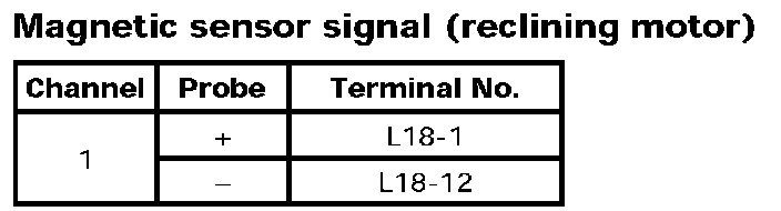
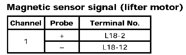
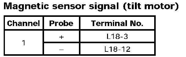
3. Check terminal voltages and output waveforms using voltmeter and oscilloscope function of SUZUKI scan tool.
NOTE:
- Confirm that battery voltage is 11 V or more.
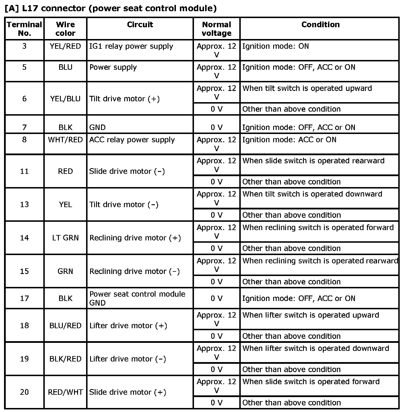
- An "ignition mode" in the following table represents a power supply mode available with the keyless push start system. For more details, refer to Description of Keyless Engine Start Function.
- Outputs from terminals marked with asterisk (*) cannot be measured with voltmeter because they are pulse signals. Use oscilloscope for measuring these outputs.

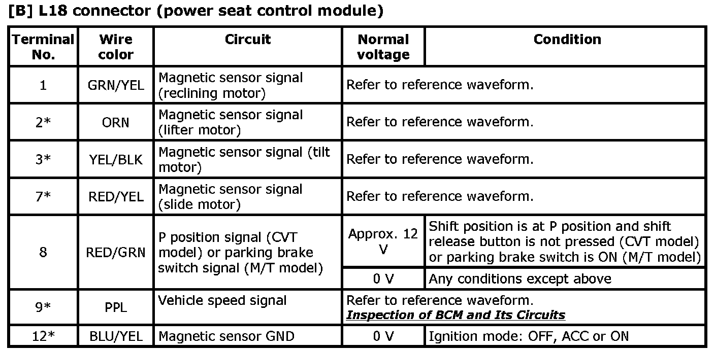
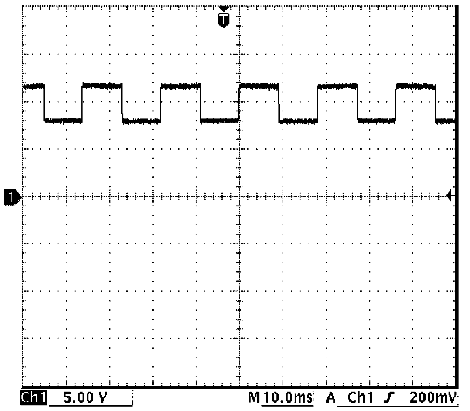
Reference Waveform
Oscilloscope display
Shown below is typical waveform display provided by oscilloscope.
NOTE:
- Display includes the following types of data:
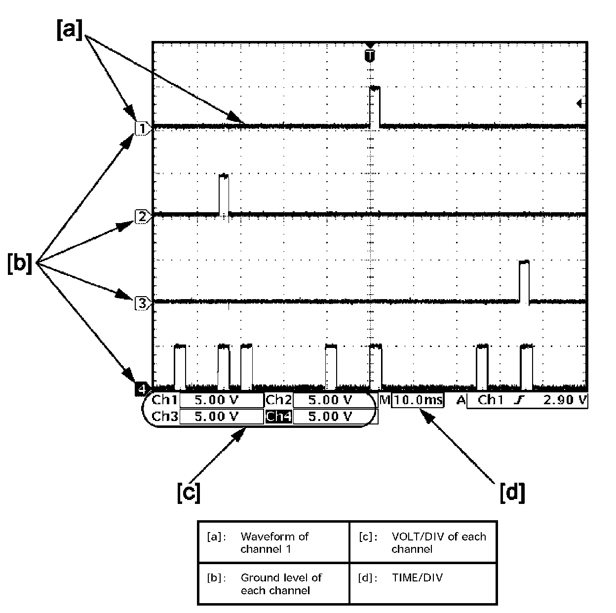
- Waveforms may vary with measurement conditions and vehicle specifications.
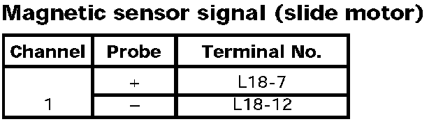
Measurement condition
- When motor is operated.