Front Steering Knuckle: Service and Repair
Knuckle: Removal and Installation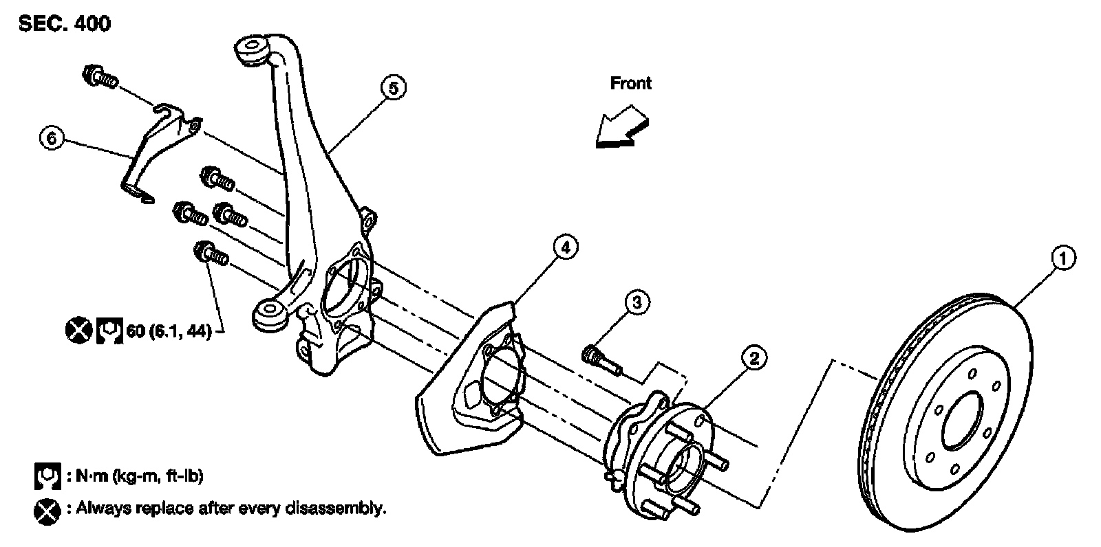
Removal
1) Remove wheel and tire from vehicle using power tool.
2) Without disassembling the hydraulic lines, remove brake caliper using power tool. Reposition it aside with wire.
NOTE:
Avoid depressing brake pedal while brake caliper is removed.
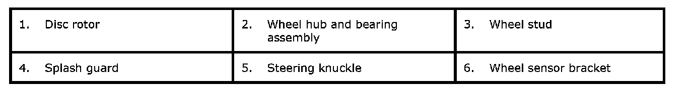
3) Put alignment marks on disc rotor and wheel hub and bearing assembly, then remove disc rotor.
4) Disconnect wheel sensor and remove bracket from steering knuckle.
CAUTION:
Do not pull on wheel sensor harness.
5) On 4WD models, remove cotter pin, then remove lock nut from drive shaft using power tool.
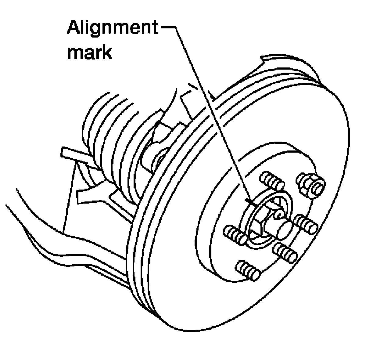
6) Remove steering outer socket cotter pin at steering knuckle, then loosen mounting nut using power tool.
7) Disconnect steering outer socket from steering knuckle using Tool. Be careful not to damage ball joint boot.
Tool number : HT72520000 (J-25730-A)
CAUTION:
To prevent damage to threads and to prevent Tool from coming off suddenly, temporarily tighten nut.
8) Remove wheel hub and bearing assembly bolts using power tool.
9) Remove splash guard and wheel hub and bearing assembly from steering knuckle.
CAUTION:
Do not pull on wheel sensor harness.
10) Remove cotter pin and nut from upper link ball joint.
11) Separate upper link ball joint from steering knuckle using Tool.
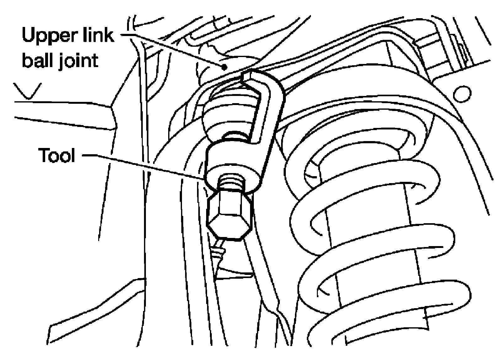
Tool number : ST29020001 (J-24319-01)
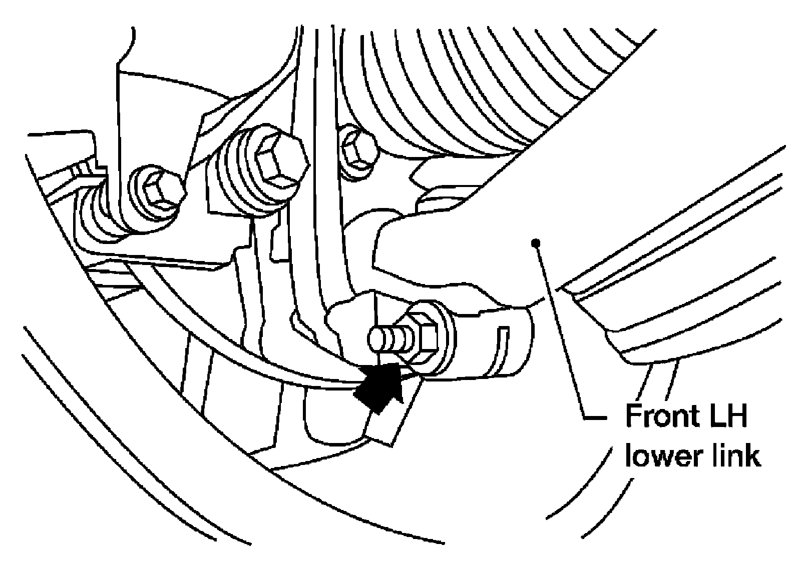
12) Remove pinch bolt from steering knuckle using power tool, then separate lower link ball joint from steering knuckle.
13) Remove steering knuckle from vehicle.
Inspection after Removal
Check for deformity, cracks and damage on each part, replace if necessary.
^ Perform ball joint inspection.
Installation
Installation is in the reverse order of removal.
^ For 4WD models, refer to [Drive Shaft: Removal and Installation] for drive shaft lock nut tightening torque.
CAUTION:
Always replace drive shaft lock nut and cotter pin.
^ Refer to [Steering Gear and Linkage: Disassembly and Assembly] for outer socket nut tightening torque.
^ Refer to [Front Suspension Assembly: Component] for front suspension tightening torques.
^ When installing disc rotor on wheel hub and bearing assembly, align the marks.
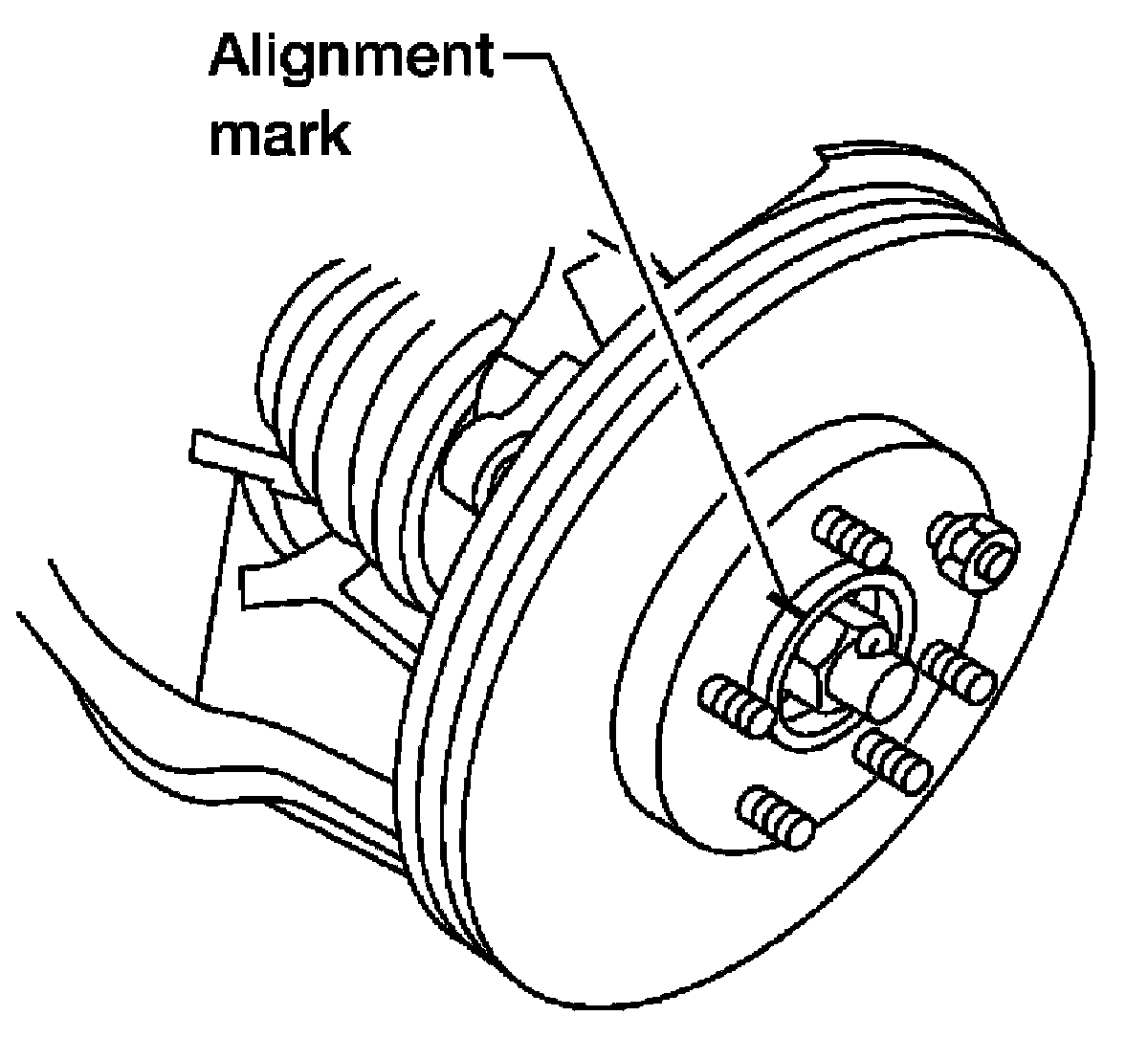
NOTE:
When not using the alignment mark! refer to [Service Data and Specifications].
^ When installing wheel and tire, refer to [Wheel and Tire Assembly: Rotation].
^ Perform wheel alignment.