P0032
P0031, P0032 A/F Sensor 1 HeaterDescription
System Description
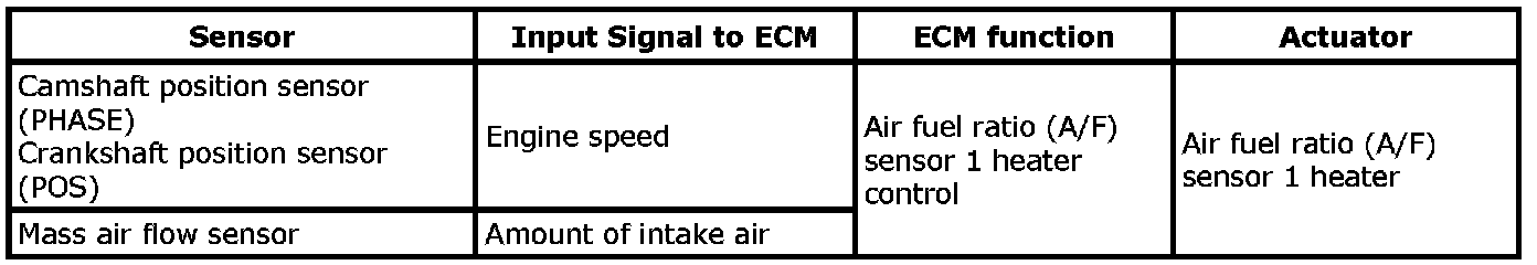
The ECM performs ON/OFF duty control of the A/F sensor 1 heater corresponding to the engine operating condition to keep the temperature of A/F sensor 1 element at the specified range.
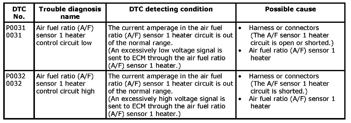
On Board Diagnosis Logic
P0031-P0032:
DTC Confirmation Procedure
NOTE: If DTC Confirmation Procedure has been previously conducted, always turn ignition switch OFF and wait at least 10 seconds before conducting the next test.
TESTING CONDITION:
Before performing the following procedure, confirm that battery voltage is between 10.5V and 16V at idle.
With SDT
1. Start engine and run it for at least 10 seconds at idle speed.
2. Check 1st trip DTC.
3. If 1st trip DTC is detected, go to [P0031, P0032 A/F Sensor 1 Heater].
With GST
Follow the procedure "With SDT" above.
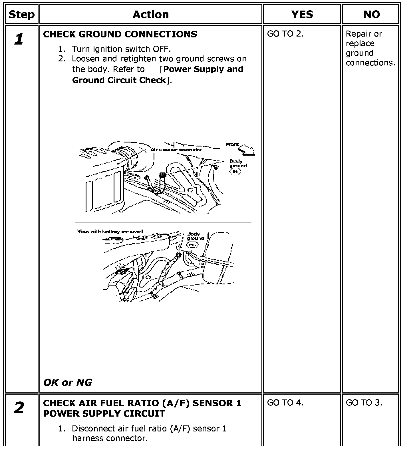
Diagnosis Procedure
Step 1-2:
Step 2 (Continued)-4:
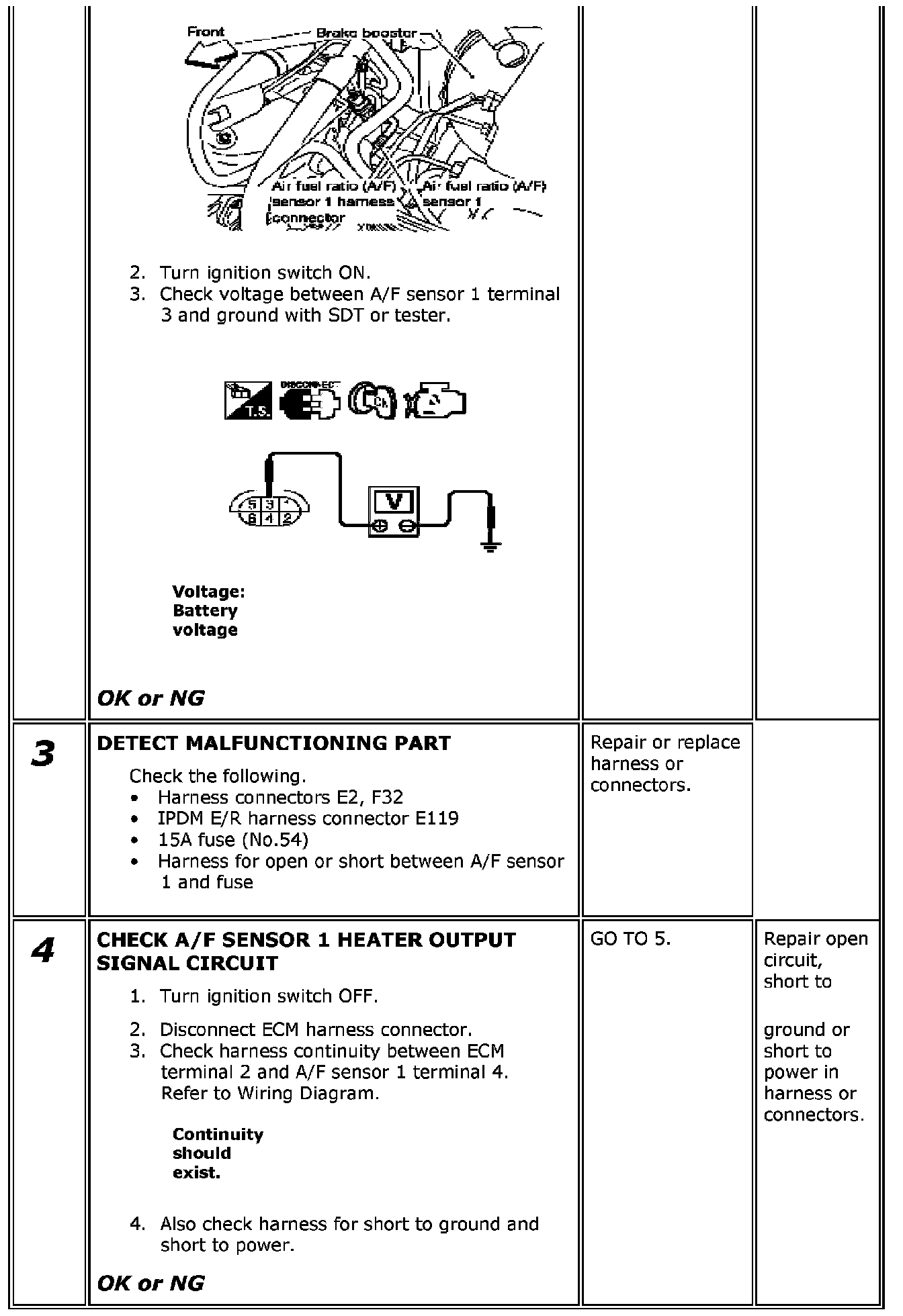
Step 5-7:
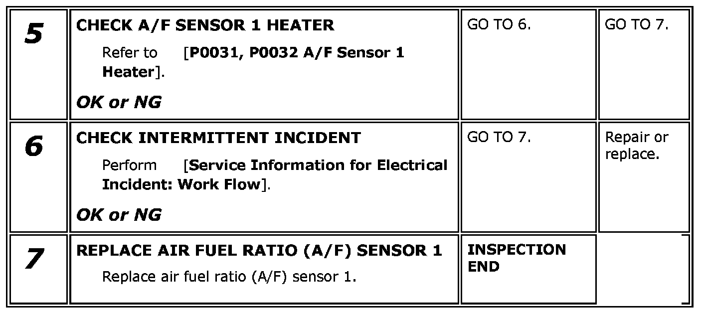
Component Inspection
A/F Sensor 1 Heater
Check resistance between terminals 3 and 4.
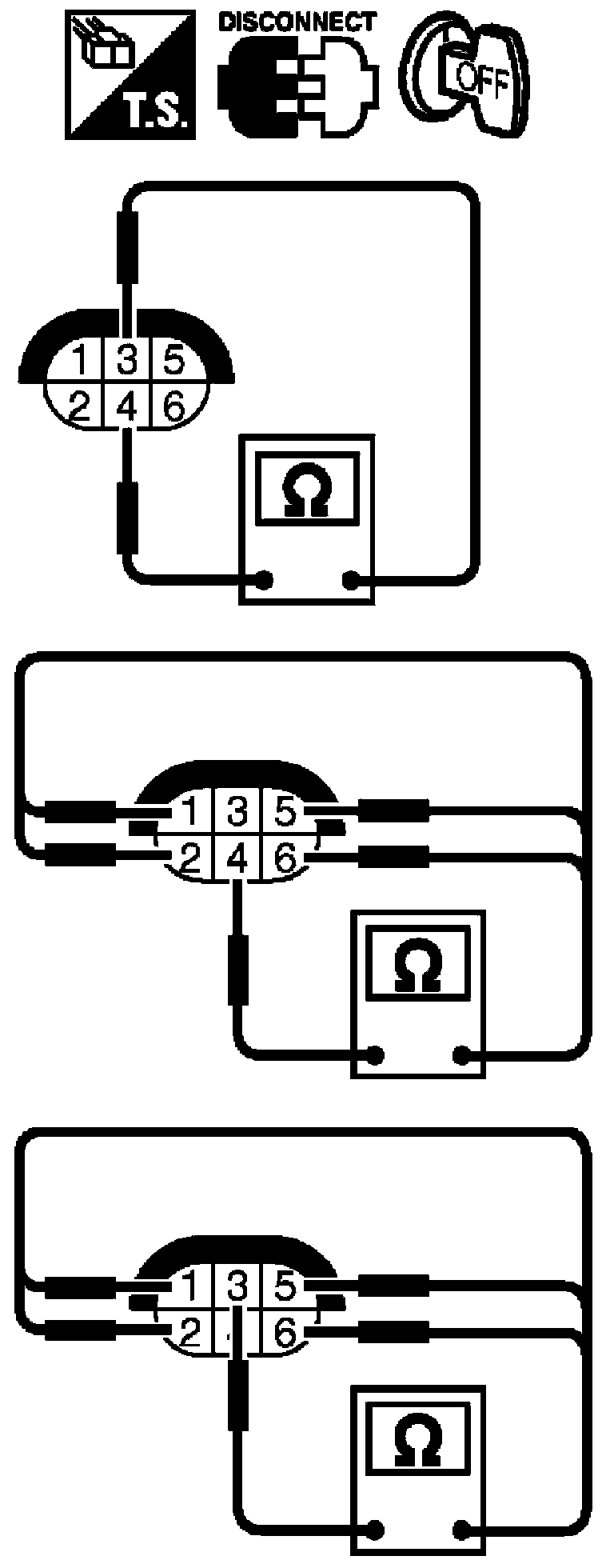
Resistance: 2.3 - 4.3 ohms [at 25 °C (77 °F)]
Check continuity between terminals 3 and 1, 2, 5, 6, terminals 4 and 1, 2, 5, 6.
Continuity should not exist.
If NG, replace the A/F sensor 1.
CAUTION:
- Discard any A/F sensor which has been dropped from a height of more than 0.5 m (19.7 in) onto a hard surface such as a concrete floor; use a new one.
- Before installing new A/F sensor, clean exhaust system threads using Heated Oxygen Sensor Thread Cleaner [commercial service tool (J-43897-18 or J-43897-12)] and approved anti-seize lubricant (commercial service tool).