Intake Manifold Removal and Installation
Intake Manifold Removal and InstallationRemoval
1) Relieve fuel pressure.
2) Disconnect negative cable at battery.
3) Remove engine cover.
CAUTION:
When removing engine cover, be sure to lift up its front side to prevent breakage of engine cover claws.
4) Drain coolant.
5) Remove throttle body assembly.
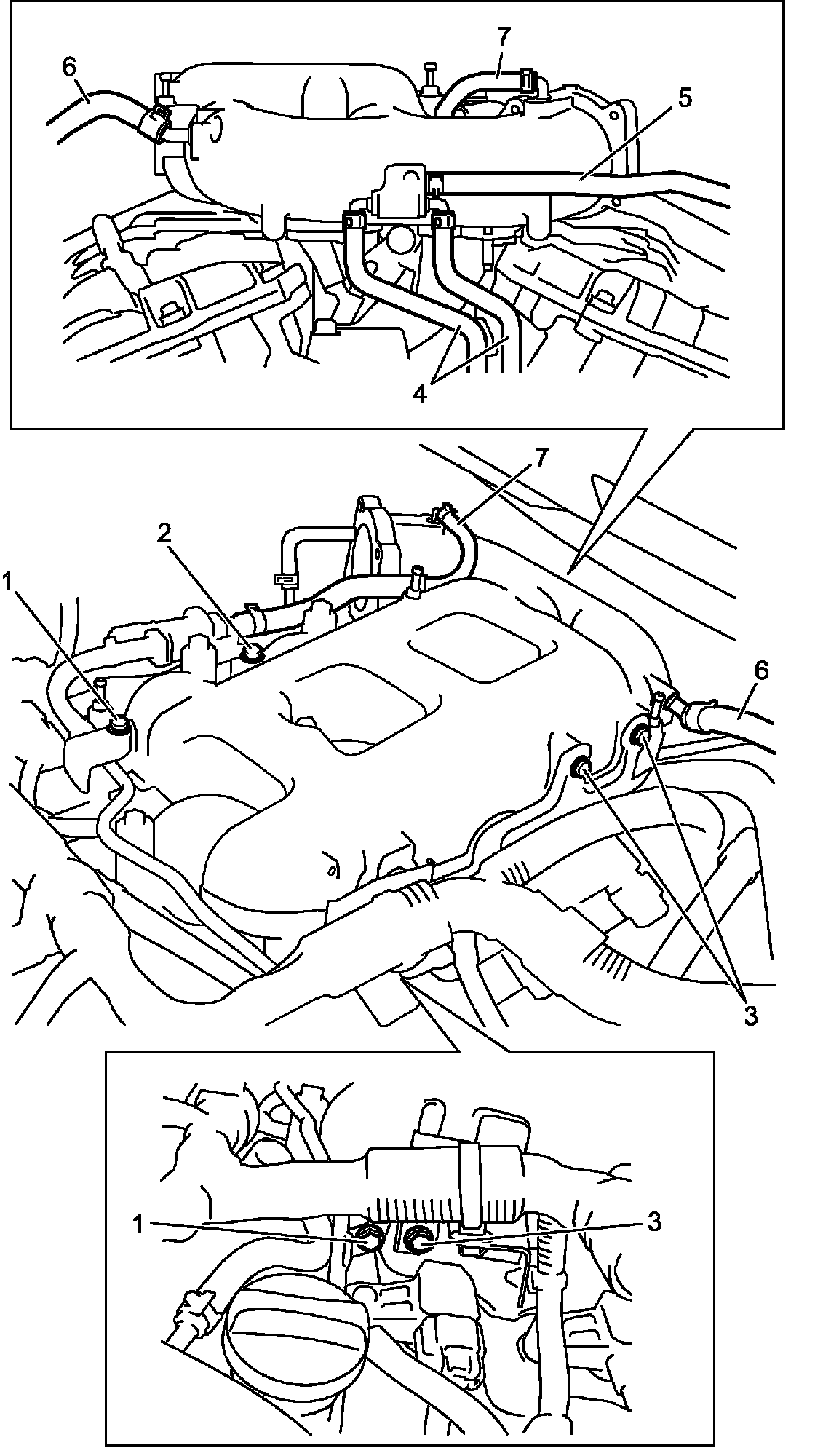
6) Remove the following parts.
^ Purge pipe bolt (1)
^ Purge valve bracket bolt (2)
^ Electric wire bracket bolt (3)
^ Water bypass hose (4)
^ PCV hose (5)
^ Brake booster hose (6)
^ Purge hose (7)
7) Remove intake upper manifold and intake manifold upper gasket.
8) Remove fuel injectors. '
9) Remove intake lower manifold and intake manifold lower gasket.
Installation
Reverse removal procedure for installation noting the following.
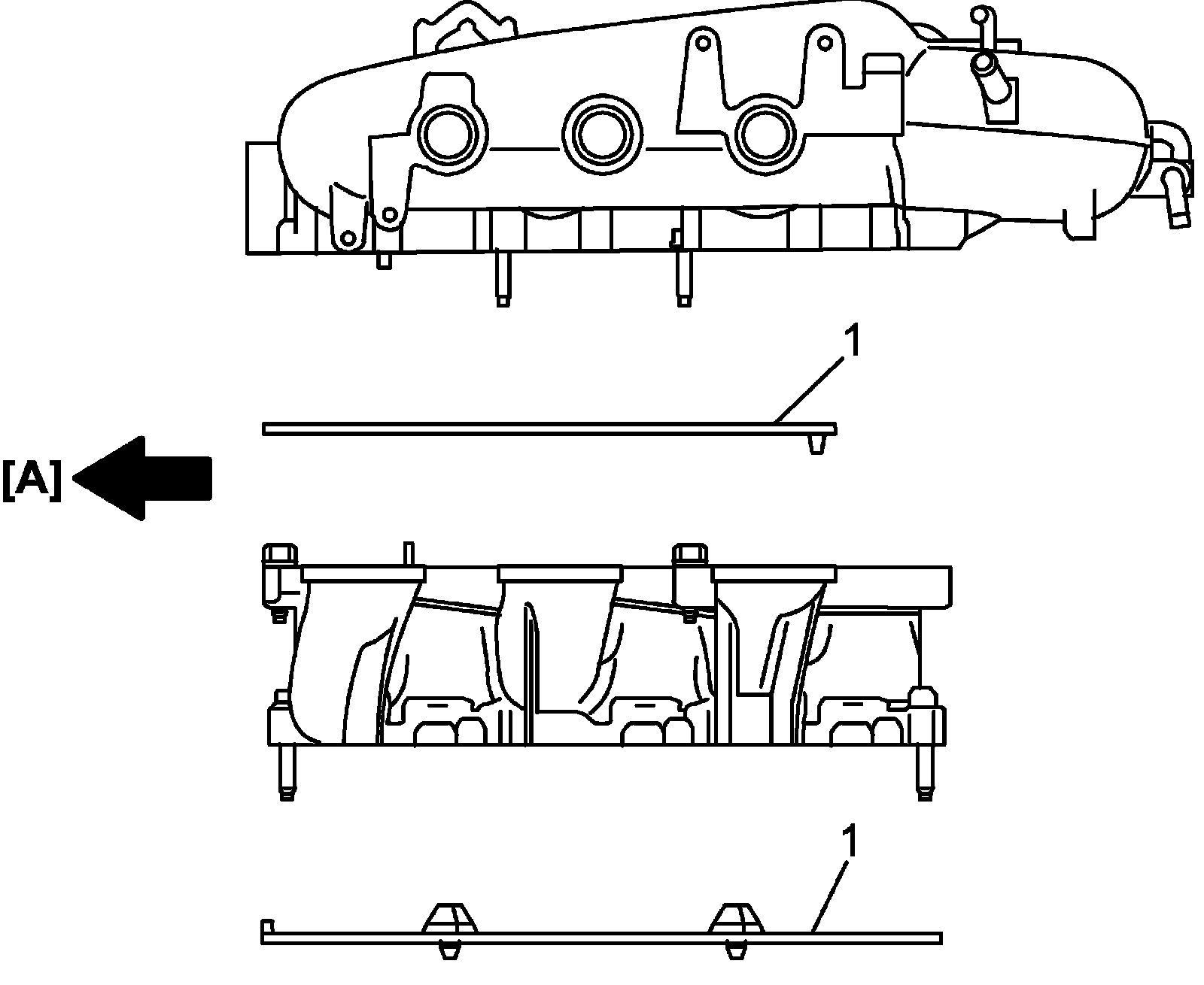
^ Install new gaskets (1) as shown in figure.

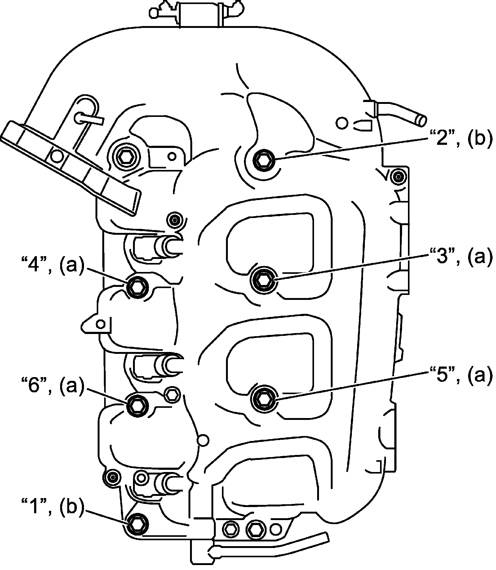
^ Tighten intake manifold bolt as follows.
a. Tighten intake manifold bolts (No.1 and No.2) to 10 Nm (1.0 kgf-m, 7.5 lbf-ft) in numerical order ("1" - "6") shown in figure evenly and gradually.
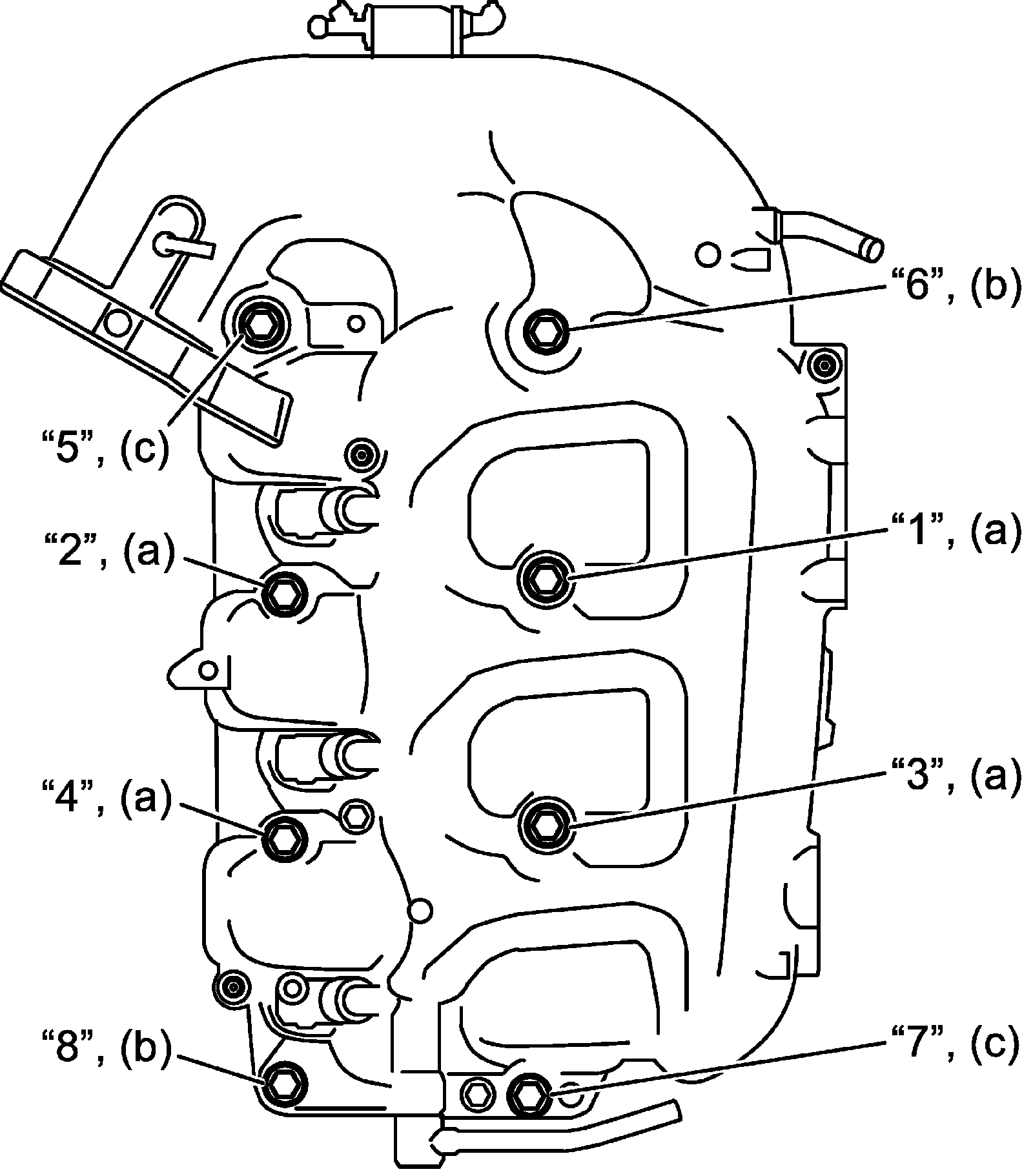
b. Tighten intake manifold bolts (No.1, No.2 and No.3) to 25 Nm (2.5 kgf-m, 18.5 lbf-ft) in numerical order ("1" - "8") shown in figure evenly and gradually.
Tightening torque
Intake manifold bolt No.1* (a): 10 Nm -> 25 Nm (1.0 kgf-m -> 2.5 kgf-m, 7.5 lbf-ft -> 18.5 lbf-ft)
Intake manifold bolt No.2* (b): 10 Nm -> 25 Nm (1.0 kgf-m -> 2.5 kgf-m, 7.5 lbf-ft -> 18.5 lbf-ft)
Intake manifold bolt No.3* (c): 25 Nm (2.5 kg-m, 18.5 lbf-ft)
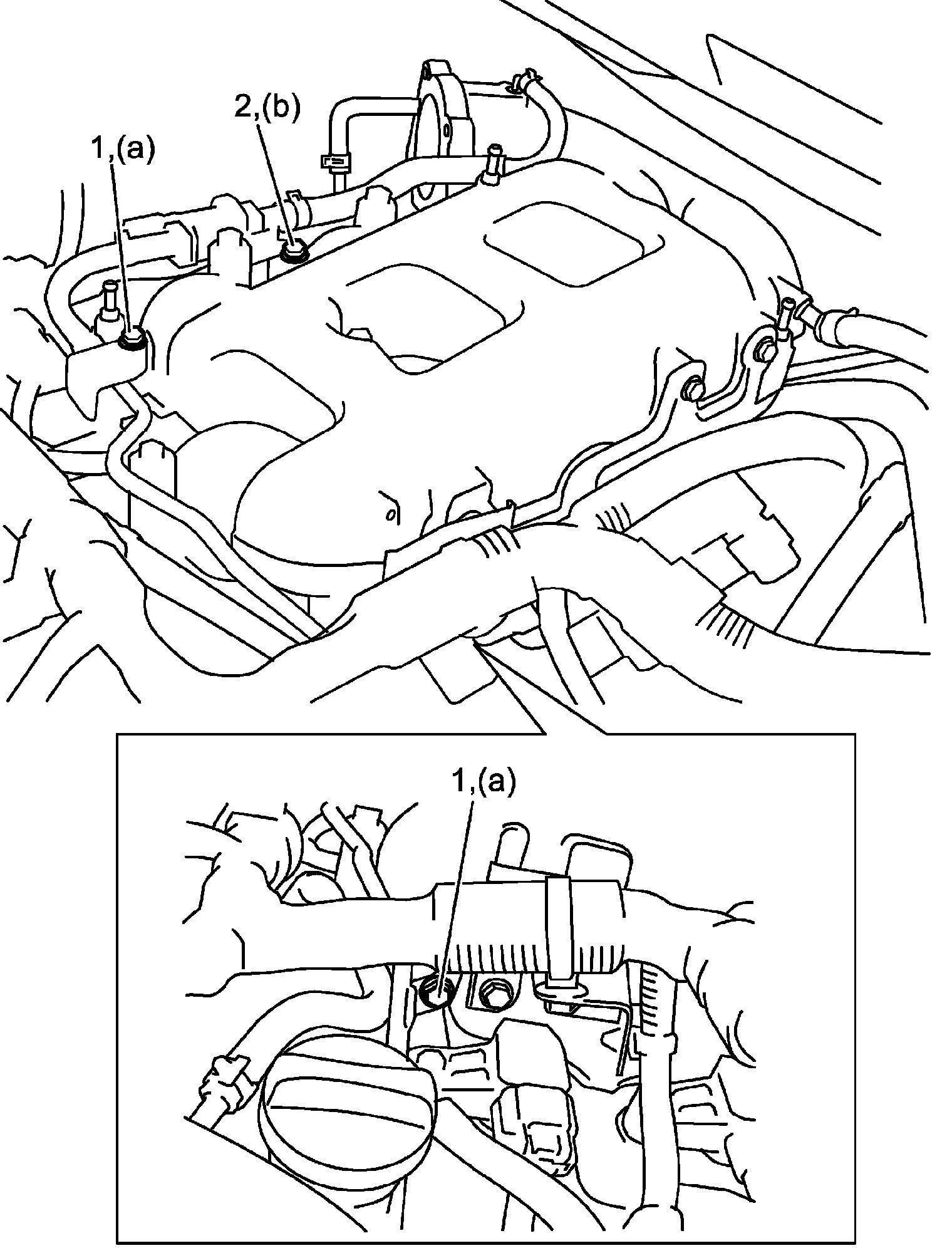
^ Tighten purge pipe bolt (1) and purge valve bracket bolt (2) to specified torque.
Tightening torque
Purge pipe bolt (a): 10 Nm (1.0 kg-m, 7.5 lbf-ft)
Purge valve bracket bolt (b): 10 Nm (1.0 kg-m, 7.5 lbf-ft)
^ Check to ensure that all removed parts are back in place.
^ Upon completion of installation, turn ignition switch ON position without starting engine and check for fuel leaks.
^ Finally, start engine and check for engine coolant leaks.