Hydraulic Control Assembly - Antilock Brakes: Service and Repair
ABS (ESP@) Hydraulic Unit Control Module Assembly Removal and InstallationCAUTION:
^ Do not give an impact to hydraulic unit.
^ Use care not to allow dust to enter ABS (ESP@) hydraulic unit control module assembly.
^ Do not place ABS (ESP@) hydraulic unit control module assembly on its side or upside down.
^ Handling it in inappropriate way will affect its original performance.
^ Never disassemble ABS (ESP@) hydraulic unit control module assembly, loosen blind plug or remove motor. Performing any of these prohibited services will affect original performance of ESP@ hydraulic unit control module assembly.
^ Do not allow brake fluid to get on painted surfaces. Painted surfaces will be damaged by brake fluid, flush it with water immediately if any fluid is spilled.
^ Be sure to tighten fastener to specified torque using torque wrench to avoid damage.
NOTE:
^ For ESP@ model, be sure to perform Sensor Calibration before performing hydraulic unit operation check when ESP@ hydraulic unit control module is replaced.
^ When ignition switch is turned to ON position after replacing ESP@ hydraulic unit control module, DTC C1075, C1076, C1078 and C1077 are stored in ESP@ control module and the indicator lights light up or flash. However, these are in normal operation. These DTCs are cleared and lights are turned off if the following operations are performed in order.
1) Sensor Calibration.
2) ABS Hydraulic Unit Operation Check.
3) Ignition switch OFF and ON.
Removal
1) Disconnect negative cable from battery.
2) Remove ECM referring to Engine Control Module (ECM) Removal and Installation:N32A or ECM (Engine Control Module) Removal and Installation.J24B.
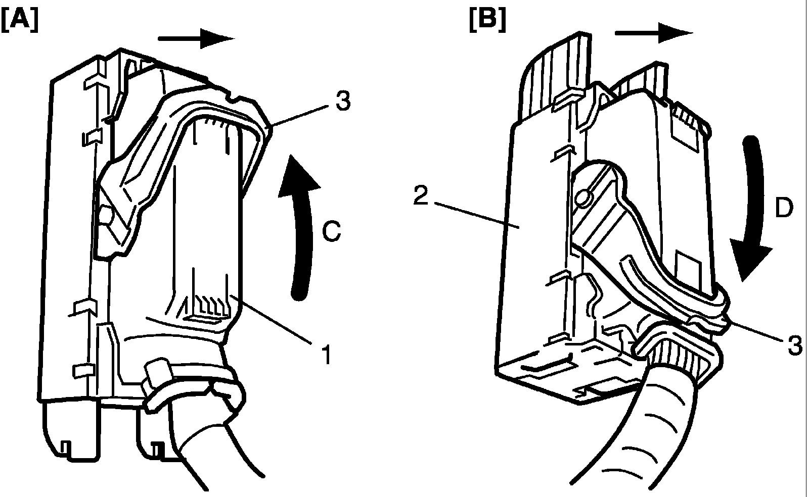
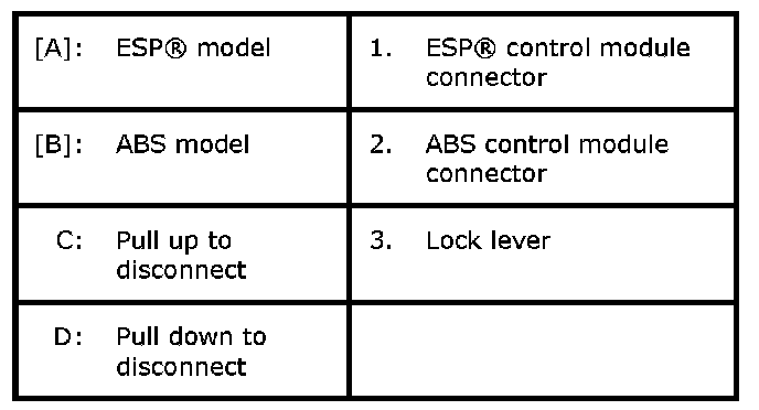
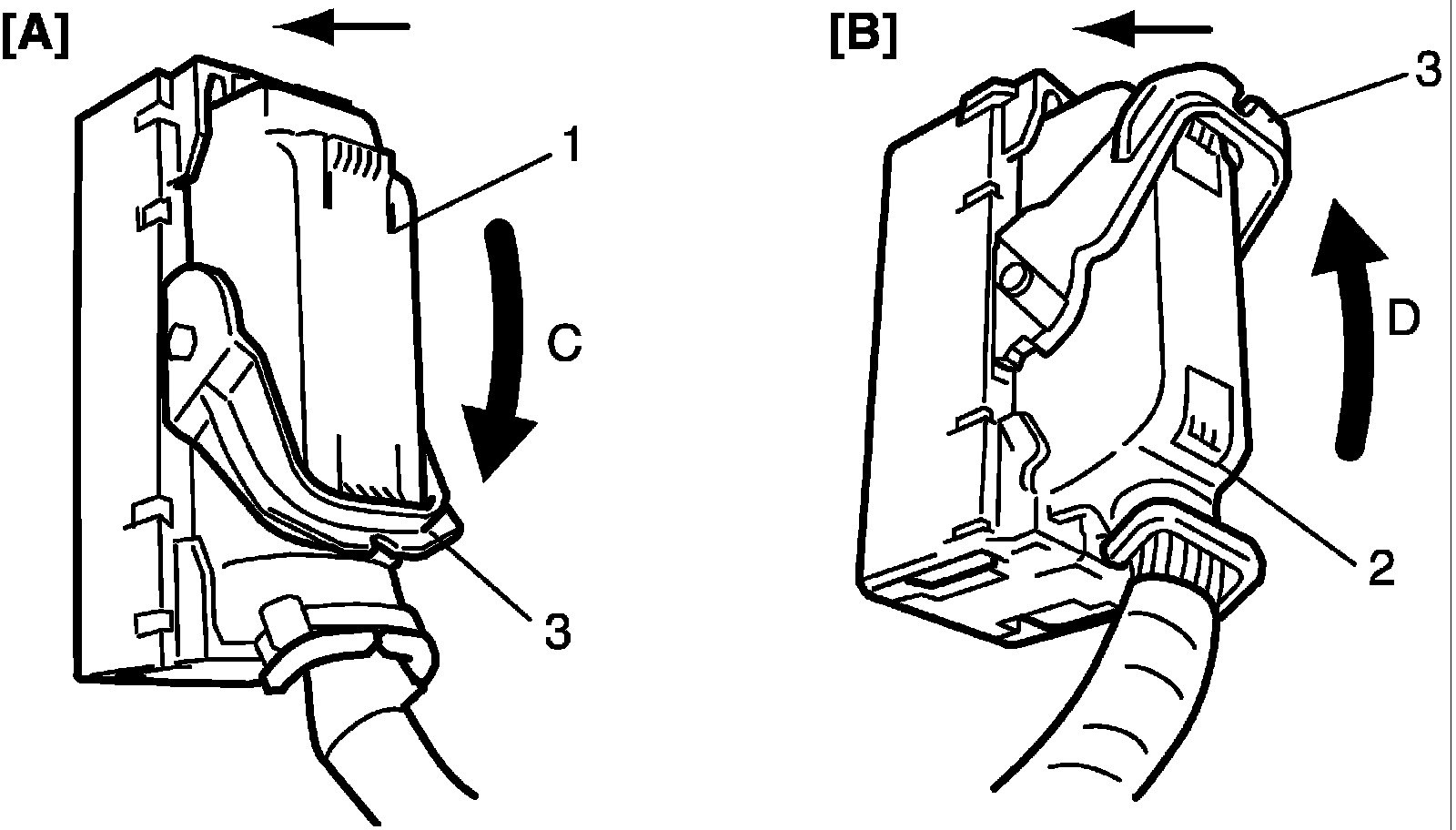
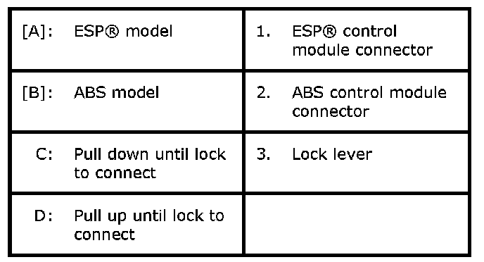
3) Disconnect ABS ESP (R) control module connector as shown in figure.
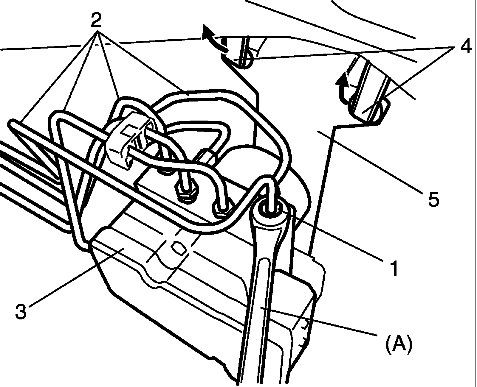
4) Using special tool, loosen flare nuts (1) and disconnect brake pipes (2) from ABS ESP (R) hydraulic unit/ control module assembly (3).
Special Tool
(A): 09950-78220
NOTE:
Put bleeder plug cap or the like onto pipe to prevent fluid from spilling.
5) Disconnect harness clamps (4) from bracket (5).
6) Remove ABS ESP (R) hydraulic unit control module with bracket from vehicle by removing bracket bolt and two bracket nuts.
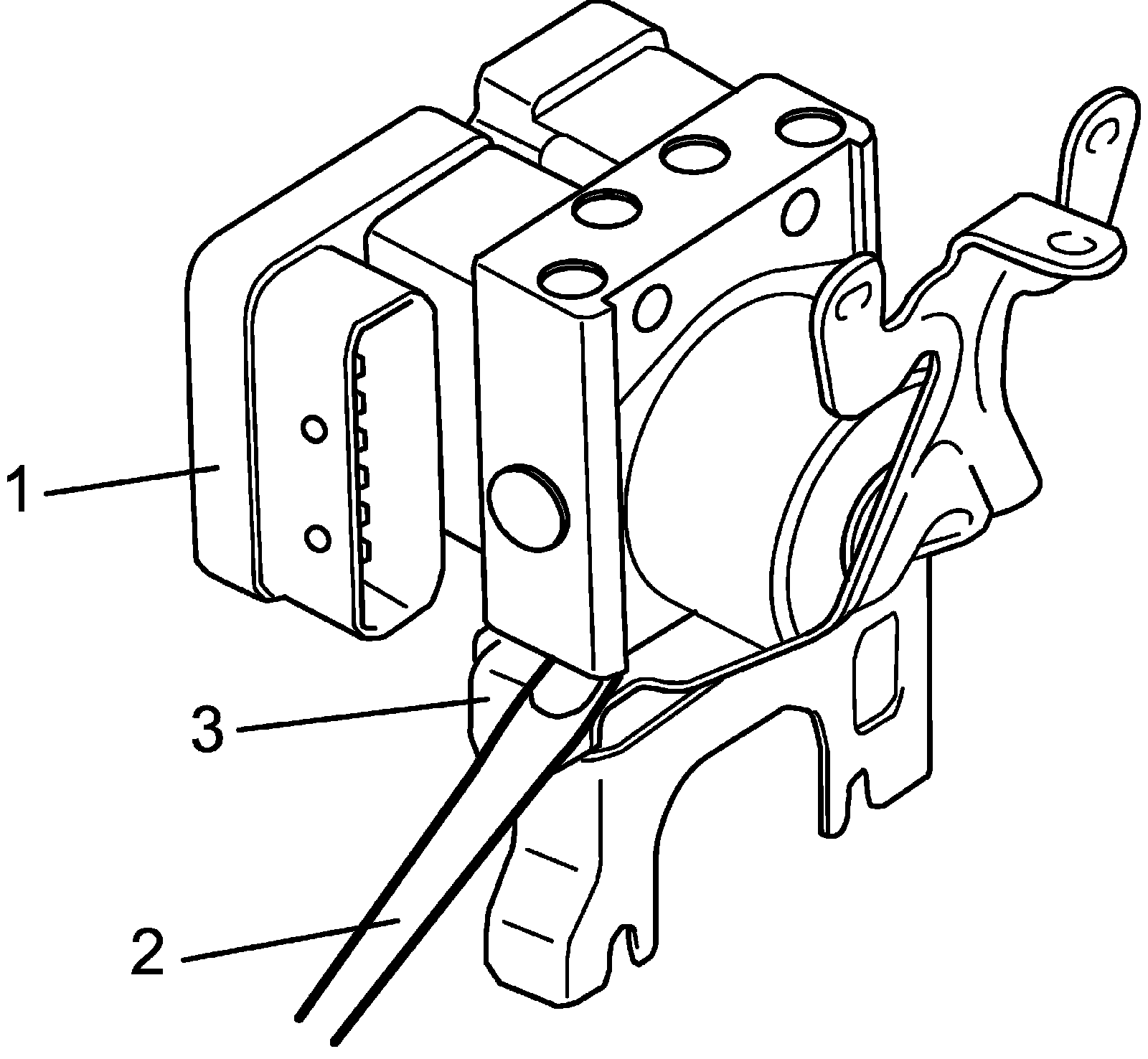
7) Remove bolt and pull out ABS ESP (R) hydraulic unit control module assembly (1) from bracket (3) using flat end rod or the like (2).
Installation
1) Install hydraulic unit control module assembly by reversing removal procedure.
Tightening torque
Brake pipe flare nut for M10: 16 Nm (1.6 kg-m, 12.0 ft. lbs.)
Brake pipe flare nut for M12: 19 Nm (1.9 kg-m, 14.0 ft. lbs.)
ABS (ESP@) hydraulic unit control module assembly bolt: 9 Nm (0.9 kg-m, 7.0 ft. lbs.)
ABS (ESP@) hydraulic unit control module assembly bracket bolt: 25 Nm (2.5 kg-m, 18.5 ft. lbs.)
ABS (ESP@) hydraulic unit control module assembly bracket nut: 25 Nm (2.5 kg-m, 18.5 ft. lbs.)
2) Connect ABS ESP (R) control module connector and lock it as shown in figure.
3) Connect harness clamp to bracket.
4) Install ECM referring to Engine Control Module (ECM) Removal and Installation:N32A or ECM (Engine Control Module) Removal and Installation.J24B.
5) Connect negative cable at battery.
6) Bleed air from brake system.
7) Check each installed part for fluid leakage.
8) For ESP (R) model, perform Sensor Calibration.
9) Perform ABS Hydraulic Unit Operation Check or ESP@ Hydraulic Unit Operation Check.
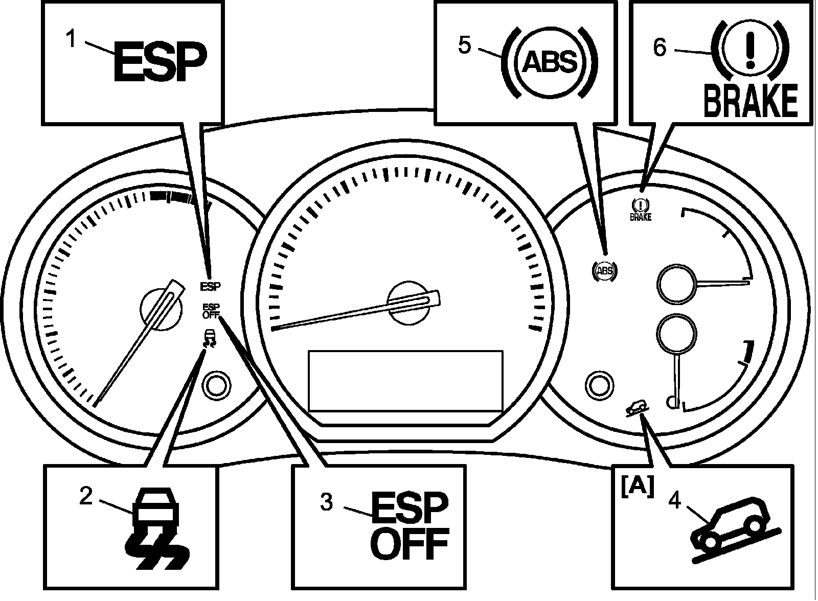
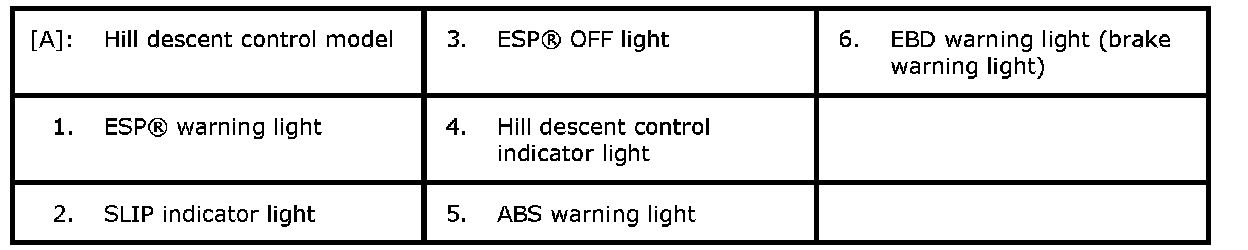
10) Turn ignition switch to OFF position once and then ON position. In this state, make sure that warning indicator lights are turn off.
11) Check DTC(s) are not stored in hydraulic unit control module.