| 1 |
CHECK OVERALL FUNCTION-I
- With SDT
- Turn ignition switch ON.
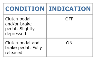
- Select "BRAKE SW1" in "Data list" mode with SDT.
- Check "BRAKE SW1" indication under the following conditions.
   Courtesy of SUZUKI OF AMERICA CORP.SUZUKI OF AMERICA CORP.SUZUKI OF AMERICA CORP. Courtesy of SUZUKI OF AMERICA CORP.SUZUKI OF AMERICA CORP.SUZUKI OF AMERICA CORP.
- 2)
Without SDT
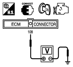
- Turn ignition switch ON.
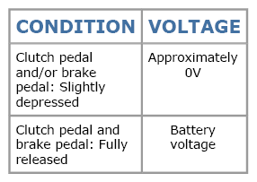
- Check voltage between ECM terminal 108 and ground under the following conditions.
Courtesy of SUZUKI OF AMERICA CORP.SUZUKI OF AMERICA CORP.SUZUKI OF AMERICA CORP.
Courtesy of SUZUKI OF AMERICA CORP.SUZUKI OF AMERICA CORP.SUZUKI OF AMERICA CORP.
OK or NG |
GO TO 2. |
GO TO 3. |
| 2 |
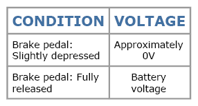
CHECK OVERALL FUNCTION-II
- With SDT
Check "BRAKE SW2" indication in "Data list" mode.
- Without SDT
Check voltage between ECM terminal 101 and ground under the following conditions.
OK or NG |
GO TO 14. |
GO TO 10. |
| 3 |
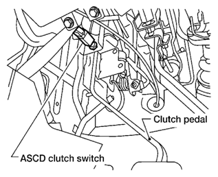
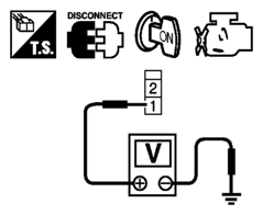
CHECK ASCD CLUTCH SWITCH POWER SUPPLY CIRCUIT
- Turn ignition switch OFF.
- Disconnect ASCD clutch switch harness connector.
   Courtesy of SUZUKI OF AMERICA CORP.SUZUKI OF AMERICA CORP.SUZUKI OF AMERICA CORP. Courtesy of SUZUKI OF AMERICA CORP.SUZUKI OF AMERICA CORP.SUZUKI OF AMERICA CORP.
- 3. Turn ignition switch ON.
- 4. Check voltage between ASCD clutch switch terminal 1 and ground under the following conditions with SDT or tester.
Courtesy of SUZUKI OF AMERICA CORP.SUZUKI OF AMERICA CORP.SUZUKI OF AMERICA CORP.
Courtesy of SUZUKI OF AMERICA CORP.SUZUKI OF AMERICA CORP.SUZUKI OF AMERICA CORP.
OK or NG |
GO TO 8. |
GO TO 4. |
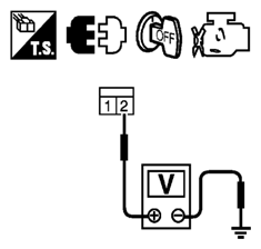
| 4 |
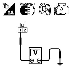
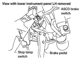
CHECK ASCD BRAKE SWITCH POWER SUPPLY CIRCUIT
- Turn ignition switch OFF.
- Disconnect ASCD brake switch harness connector.
  Courtesy of SUZUKI OF AMERICA CORP.SUZUKI OF AMERICA CORP. Courtesy of SUZUKI OF AMERICA CORP.SUZUKI OF AMERICA CORP.
- 3. Turn ignition switch ON.
- 4. Check voltage between ASCD brake switch terminal 1 and ground with SDT or tester.
Courtesy of SUZUKI OF AMERICA CORP.SUZUKI OF AMERICA CORP.
Voltage: Battery voltage
OK or NG |
GO TO 6. |
GO TO 5. |
| 5 |
DETECT MALFUNCTIONING PART
Check the following.
- Fuse block (J/B) connector F160
- 10 A fuse (No. 12)
- Harness for open or short between ASCD brake switch and fuse
|
Repair open circuit or short to ground in harness or connectors. |
|
| 6 |
CHECK ASCD BRAKE SWITCH INPUT SIGNAL CIRCUIT FOR OPEN AND SHORT
- Turn ignition switch OFF.
- Check harness continuity between ASCD brake switch terminal 2 and ASCD clutch switch terminal 1. Refer to WIRING DIAGRAM
.
Continuity should exist.
- Also check harness for short to ground and short to power.
OK or NG |
GO TO 7. |
Repair open circuit or short to ground or short to power in harness or connectors. |
| 7 |
CHECK ASCD BRAKE SWITCH
Refer to
[P1572 ASCD BRAKE SWITCH ].
OK or NG |
GO TO 14. |
Replace ASCD brake switch. |
| 8 |
CHECK ASCD BRAKE SWITCH INPUT SIGNAL CIRCUIT FOR OPEN AND SHORT
- Turn ignition switch OFF.
- Disconnect ECM harness connector.
- Check harness continuity between ECM terminal 108 and ASCD clutch switch terminal 2.
Refer to WIRING DIAGRAM
.
Continuity should exist.
- Also check harness for short to ground and short to power.
OK or NG |
GO TO 9. |
Repair open circuit or short to ground or short to power in harness or connectors. |
| 9 |
CHECK ASCD CLUTCH SWITCH
Refer to
[P1572 ASCD BRAKE SWITCH ].
OK or NG |
GO TO 14. |
Replace ASCD clutch switch. |
| 10 |
CHECK STOP LAMP SWITCH POWER SUPPLY CIRCUIT
- Turn ignition switch OFF.
- Disconnect stop lamp switch harness connector.
  Courtesy of SUZUKI OF AMERICA CORP.SUZUKI OF AMERICA CORP. Courtesy of SUZUKI OF AMERICA CORP.SUZUKI OF AMERICA CORP.
- 3. Check voltage between stop lamp switch terminal 2 and ground with SDT or tester.
Courtesy of SUZUKI OF AMERICA CORP.SUZUKI OF AMERICA CORP.
Voltage: Battery voltage
OK or NG |
GO TO 12. |
GO TO 11. |
| 11 |
DETECT MALFUNCTIONING PART
Check the following.
- Fuse block (J/B) connector F160
- 10 A fuse (No. 20)
- Harness for open or short between stop lamp switch and battery
|
Repair open circuit or short to ground or short to power in harness or connectors. |
|
| 12 |
CHECK STOP LAMP SWITCH INPUT SIGNAL CIRCUIT FOR OPEN AND SHORT
- Disconnect ECM harness connector.
- Check harness continuity between ECM terminal 101 and stop lamp switch terminal 2.
Refer to WIRING DIAGRAM
.
Continuity should exist.
- Also check harness for short to ground and short to power.
OK or NG |
GO TO 13. |
Repair open circuit or short to ground or short to power in harness or connectors. |
| 13 |
CHECK STOP LAMP SWITCH
Refer to
[P1572 ASCD BRAKE SWITCH ].
OK or NG |
GO TO 14. |
Replace stop lamp switch. |
| 14 |
CHECK INTERMITTENT INCIDENT
Refer to
[SERVICE INFORMATION FOR ELECTRICAL INCIDENT: INTERMITTENT INCIDENT
] |
INSPECTION END |
|