| 1 |
CHECK ENGINE START
Turn ignition switch OFF, and restart engine.
Is engine running?
Yes or No |
GO TO 2. |
GO TO 3. |
| 2 |
CHECK OVERALL FUNCTION
With SDT
- Perform "POWER BALANCE" in "Active test" mode with SDT.
- Make sure that each circuit produces a momentary engine speed drop.
OK or NG |
INSPECTION END |
GO TO 10. |
| 3 |
CHECK OVERALL FUNCTION
Without SDT
- Let engine idle.
- Read the voltage signal between ECM terminals 60, 61, 62, 79, 80, 81 and ground with an oscilloscope.
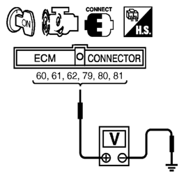 Courtesy of SUZUKI OF AMERICA CORP. Courtesy of SUZUKI OF AMERICA CORP.
- 3. Verify that the oscilloscope screen shows the signal wave as shown below.
NOTE:
The pulse cycle changes depending on RPM at idle.
OK or NG |
INSPECTION END |
GO TO 10. |
| 4 |
CHECK IGNITION COIL POWER SUPPLY CIRCUIT-I
- Turn ignition switch OFF, wait at least 10 seconds and then turn it ON.
- Check voltage between ECM terminals 119, 120 and ground with SDT or tester.
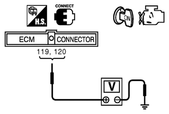 Courtesy of SUZUKI OF AMERICA CORP. Courtesy of SUZUKI OF AMERICA CORP.
Voltage: Battery voltage
OK or NG |
GO TO 5. |
Go to
[POWER SUPPLY AND GROUND CIRCUIT CHECK
]. |
| 5 |
CHECK IGNITION COIL POWER SUPPLY CIRCUIT-II
- Turn ignition switch OFF.
- Disconnect condenser-1 harness connector.
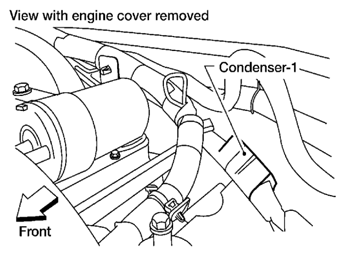  Courtesy of SUZUKI OF AMERICA CORP.SUZUKI OF AMERICA CORP. Courtesy of SUZUKI OF AMERICA CORP.SUZUKI OF AMERICA CORP.
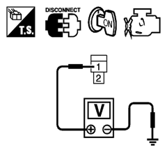
- 3. Turn ignition switch ON.
- 4. Check voltage between condenser-1 terminal 1 and ground with SDT or tester.
Courtesy of SUZUKI OF AMERICA CORP.SUZUKI OF AMERICA CORP.
Voltage: Battery voltage
OK or NG |
GO TO 8. |
GO TO 6. |
| 6 |
CHECK IGNITION COIL POWER SUPPLY CIRCUIT-III
- Turn ignition switch OFF.
- Disconnect IPDM E/R harness connector E119.
- Check harness continuity between IPDM E/R terminal 3 and condenser-1 terminal 1. Refer to WIRING DIAGRAM
.
Continuity should exist.
- Also check harness for short to ground and short to power.
OK or NG |
GO TO 17. |
GO TO 7. |
| 7 |
DETECT MALFUNCTIONING PART
Check the following.
- Harness connectors E2, F32
- Harness for open or short between condenser-1 and IPDM E/R
|
Repair open circuit or short to ground or short to power in harness or connectors. |
|
| 8 |
CHECK CONDENSER-1 GROUND CIRCUIT FOR OPEN AND SHORT
- Turn ignition switch OFF.
- Check harness continuity between condenser-1 terminal 2 and ground.
Refer to WIRING DIAGRAM
.
Continuity should exist.
- Also check harness for short to power.
OK or NG |
GO TO 9. |
Repair open circuit or short to power in harness or connectors. |
| 9 |
CHECK CONDENSER-1
Refer to
[IGNITION SIGNAL CIRCUIT CHECK ].
OK or NG |
GO TO 10. |
Replace condenser-1. |
| 10 |
CHECK IGNITION COIL POWER SUPPLY CIRCUIT-V
- Turn ignition switch OFF.
- Reconnect all harness connectors disconnected.
- Disconnect ignition coil harness connector.
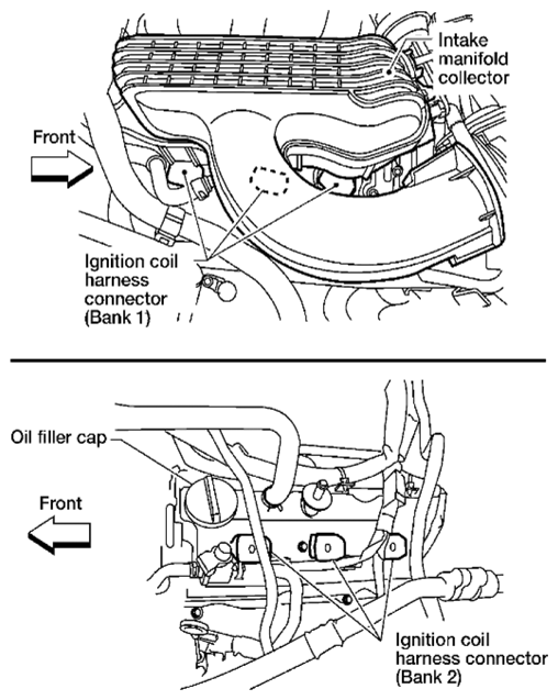  Courtesy of SUZUKI OF AMERICA CORP.SUZUKI OF AMERICA CORP. Courtesy of SUZUKI OF AMERICA CORP.SUZUKI OF AMERICA CORP.
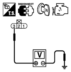
- 4. Turn ignition switch ON.
- 5. Check voltage between ignition coil terminal 3 and ground with SDT or tester.
Courtesy of SUZUKI OF AMERICA CORP.SUZUKI OF AMERICA CORP.
Voltage: Battery voltage
OK or NG |
GO TO 12. |
GO TO 11. |
| 11 |
DETECT MALFUNCTIONING PART
Check the following.
- Harness connectors F26, F225
- Harness for open or short between ignition coil and harness connector F32
|
Repair or replace harness or connectors. |
|
| 12 |
CHECK IGNITION COIL GROUND CIRCUIT FOR OPEN AND SHORT
- Turn ignition switch OFF.
- Check harness continuity between ignition coil terminal 2 and ground.
Refer to WIRING DIAGRAM
.
Continuity should exist.
- Also check harness for short to power.
OK or NG |
GO TO 14. |
GO TO 13. |
| 13 |
DETECT MALFUNCTIONING PART
Check the following.
- Harness connectors F225, F26
- Harness for open or short between ignition coil and ground
|
Repair open circuit or short to power in harness or connectors. |
|
| 14 |
CHECK IGNITION COIL OUTPUT SIGNAL CIRCUIT FOR OPEN AND SHORT
- Disconnect ECM harness connector.
- Check harness continuity between ECM terminals 60, 61, 62, 79, 80, 81 and ignition coil terminal 1.
Refer to WIRING DIAGRAM
.
Continuity should exist.
- Also check harness for short to ground and short to power.
OK or NG |
GO TO 16. |
GO TO 15. |
| 15 |
DETECT MALFUNCTIONING PART
Check the following.
- Harness connectors F26, F225
- Harness for open or short between ignition coil and ECM
|
Repair open circuit or short to ground or short to power in harness or connectors. |
|
| 16 |
CHECK IGNITION COIL WITH POWER TRANSISTOR
Refer to
[IGNITION SIGNAL CIRCUIT CHECK ].
OK or NG |
GO TO 17. |
Replace malfunctioning ignition coil with power transistor. |
| 17 |
CHECK INTERMITTENT INCIDENT
Refer to
[SERVICE INFORMATION FOR ELECTRICAL INCIDENT: INTERMITTENT INCIDENT
] |
INSPECTION END |
|