| 1 |
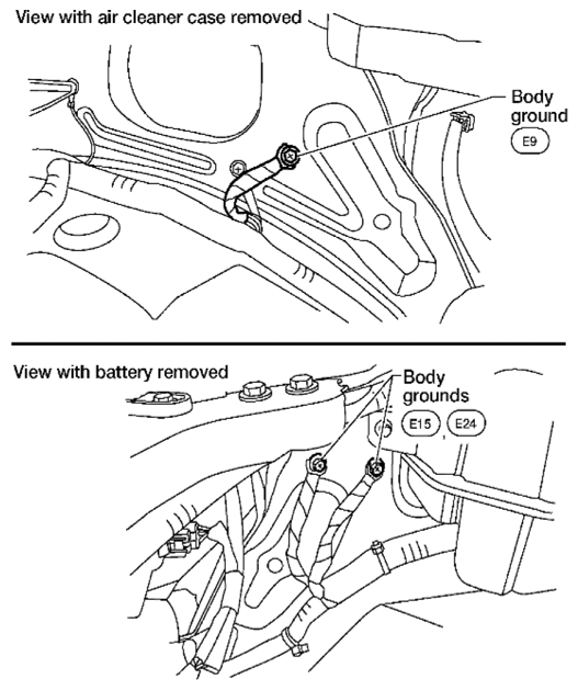
CHECK GROUND CONNECTIONS
- Turn ignition switch OFF.
- Loosen and retighten three ground screws on the body. Refer to
[POWER SUPPLY AND GROUND CIRCUIT CHECK
].
 Courtesy of SUZUKI OF AMERICA CORP. Courtesy of SUZUKI OF AMERICA CORP.
OK or NG |
GO TO 2. |
Repair or replace ground connections. |
| 2 |
RETIGHTEN AIR FUEL RATIO (A/F) SENSOR 1
Loosen and retighten the air fuel ratio (A/F) sensor 1. Refer to
[EXHAUST MANIFOLD AND THREE WAY CATALYST: REMOVAL AND INSTALLATION [VQ40DE]
] |
GO TO 3. |
|
| 3 |
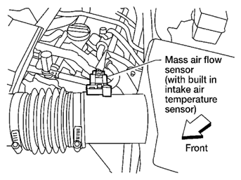
CHECK FOR INTAKE AIR LEAK
- Start engine and run it at idle.
- Listen for an intake air leak after the mass air flow sensor.
OK or NG |
GO TO 4. |
Repair or replace. |
| 4 |
CLEAR THE SELF-LEARNING DATA.
- With SDT
- Start engine and warm it up to normal operating temperature.
- Select "SELF-LEARNING CONT" in "Utility" mode with SDT.
- Clear the self-learning control coefficient by touching "Clear".
- Run engine for at least 10 minutes at idle speed.
Is the 1st trip DTC P0171, P0172, P0174 or P0175 detected? Is it difficult to start engine?
- Without SDT
- Start engine and warm it up to normal operating temperature.
- Turn ignition switch OFF.
- Disconnect mass air flow sensor harness connector.
 Courtesy of SUZUKI OF AMERICA CORP. Courtesy of SUZUKI OF AMERICA CORP.
- 4. Restart engine and let it idle for at least 3 seconds.
- 5. Stop engine and reconnect mass air flow sensor harness connector.
- 6. Make sure DTC P0102 is displayed.
- 7. Erase the DTC memory. Refer to
[EMISSION-RELATED DIAGNOSTIC INFORMATION
].
- 8. Make sure DTC P0000 is displayed.
- 9. Run engine for at least 10 minutes at idle speed.
Is the 1st trip DTC P0171, P0172 or P0174, P0175 detected?
Is it difficult to start engine?
Yes or No |
Perform trouble diagnosis for DTC P0171, P0174 or P0172, P0175. Refer to
or
. |
GO TO 5. |
| 5 |
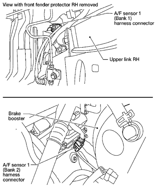
CHECK HARNESS CONNECTOR
- Turn ignition switch OFF.
- Disconnect A/F sensor 1 harness connector.
 Courtesy of SUZUKI OF AMERICA CORP. Courtesy of SUZUKI OF AMERICA CORP.
- 3. Check harness connector for water.
Water should not exit.
OK or NG |
GO TO 6. |
Repair or replace harness connector. |
| 6 |
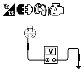
CHECK A/F SENSOR 1 POWER SUPPLY CIRCUIT
- Turn ignition switch ON.
- Check voltage between A/F sensor 1 terminal 4 and ground with SDT or tester.
 Courtesy of SUZUKI OF AMERICA CORP. Courtesy of SUZUKI OF AMERICA CORP.
Voltage: Battery voltage
OK or NG |
GO TO 8. |
GO TO 7. |
| 7 |
DETECT MALFUNCTIONING PART
Check the following.
- Harness connectors E2, F32
- IPDM E/R connector E119
- 15 A fuse (No. 54)
- Harness for open or short between A/F sensor 1 and fuse
|
Repair or replace harness or connectors. |
|
| 8 |
CHECK A/F SENSOR 1 INPUT SIGNAL CIRCUIT
- Turn ignition switch OFF.
- Disconnect ECM harness connector.
- Check harness continuity between A/F sensor 1 terminal and ECM terminal as follows.
Refer to WIRING DIAGRAM
.
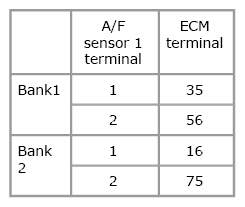 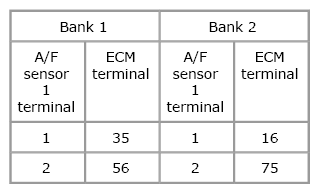 Courtesy of SUZUKI OF AMERICA CORP.SUZUKI OF AMERICA CORP. Courtesy of SUZUKI OF AMERICA CORP.SUZUKI OF AMERICA CORP.
Continuity should exist.
- 4. Check harness continuity between the following terminals and ground. Refer to WIRING DIAGRAM
.
Courtesy of SUZUKI OF AMERICA CORP.SUZUKI OF AMERICA CORP.
Continuity should not exist.
- 5. Also check harness for short to ground and short to power.
OK or NG |
GO TO 9. |
Repair open circuit or short to ground or short to power in harness or connectors. |
| 9 |
CHECK A/F SENSOR 1 HEATER
Refer to
[P0031, P0032, P0051, P0052 A/F SENSOR 1 HEATER
].
OK or NG |
GO TO 10. |
GO TO 11. |
| 10 |
CHECK INTERMITTENT INCIDENT
Perform
[SERVICE INFORMATION FOR ELECTRICAL INCIDENT: INTERMITTENT INCIDENT
]
OK or NG |
GO TO 11. |
Repair or replace. |
| 11 |
REPLACE A/F SENSOR 1
Replace malfunctioning A/F sensor 1. |
GO TO 12. |
|
| 12 |
CONFIRM A/F ADJUSTMENT DATA
- Turn ignition switch ON.
- Select "A/F ADJ-B1" and "A/F ADJ-B2" in "Data list" mode with SDT.
- Make sure that "0" is displayed on SDT screen.
OK or NG |
INSPECTION END |
GO TO 13. |
| 13 |
CREAR A/F ADJUSTMENT DATA
With SDT
- Start engine and warm it up to normal operating temperature.
- Select "SELF-LEARNING CONT" in "Utility" mode with SDT.
- Clear the self-learning control coefficient by touching "Clear".
Without SDT
- Start engine and warm it up to normal operating temperature.
- Turn ignition switch OFF.
- Disconnect mass air flow sensor harness connector.
 Courtesy of SUZUKI OF AMERICA CORP. Courtesy of SUZUKI OF AMERICA CORP.
- 4. Restart engine and let it idle for at least 5 seconds.
- 5. Stop engine and reconnect mass air flow sensor harness connector.
- 6. Make sure DTC P0102 is displayed.
- 7. Erase the DTC memory. Refer to
[EMISSION-RELATED DIAGNOSTIC INFORMATION
].
- 8. Make sure DTC P0000 is displayed.
|
GO TO 14. |
|
| 14 |
CONFIRM A/F ADJUSTMENT DATA
- Turn ignition switch OFF and then ON.
- Select "A/F ADJ-B1" and "A/F ADJ-B2" in "Data list" mode with SDT.
- Make sure that "0" is displayed on SDT screen.
OK or NG |
INSPECTION END |
|