| 1 |
CHECK KNOCK SENSOR INPUT SIGNAL CIRCUIT FOR OPEN AND SHORT-I
- Turn ignition switch OFF.
- Disconnect ECM harness connector.
- Check resistance between ECM terminals 15, 36 and ground. Refer to WIRING DIAGRAM
.
NOTE:
It is necessary to use an ohmmeter which can measure more than 10 MΩ.
Resistance:
Approximately
532 - 588 kΩ [at 20°C (68°F)]
- Also check harness for short to ground and short to power.
OK or NG |
GO TO 5. |
GO TO 2. |
| 2 |
CHECK KNOCK SENSOR INPUT SIGNAL CIRCUIT FOR OPEN AND SHORT-II
- Disconnect knock sensor harness connector.
 Courtesy of SUZUKI OF AMERICA CORP. Courtesy of SUZUKI OF AMERICA CORP.
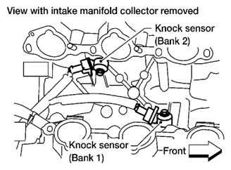
- 2. Check harness continuity between ECM terminal 15 and knock sensor (bank1) terminal 1, ECM terminal 36 and knock sensor (bank 2) terminal 1. Refer to WIRING DIAGRAM
.
Continuity should exist.
- 3. Also check harness for short to ground and short to power.
OK or NG |
GO TO 4. |
GO TO 3. |
| 3 |
DETECT MALFUNCTIONING PART
Check the following.
- Harness connectors F67, F250
- Harness for open or short between ECM and knock sensor
|
Repair open circuit or short to ground or short to power in harness or connectors. |
|
| 4 |
CHECK KNOCK SENSOR
Refer to
[P0327, P0328, P0332, P0333 KS ].
OK or NG |
GO TO 5. |
Replace malfunctioning knock sensor. |
| 5 |
CHECK GROUND CONNECTIONS
- Turn ignition switch OFF.
- Loosen and retighten three ground screws on the body. Refer to
[POWER SUPPLY AND GROUND CIRCUIT CHECK
].
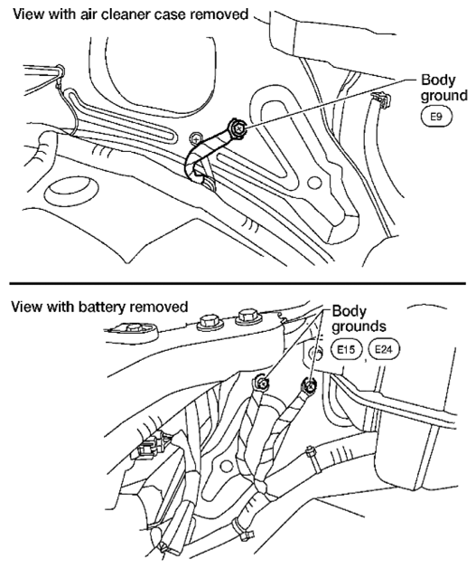 Courtesy of SUZUKI OF AMERICA CORP. Courtesy of SUZUKI OF AMERICA CORP.
OK or NG |
GO TO 6. |
Repair or replace ground connections. |
| 6 |
CHECK KNOCK SENSOR SHIELD CIRCUIT FOR OPEN AND SHORT
- Disconnect knock sensor harness connector.
- Check harness continuity between knock sensor terminal 2 and ground. Refer to WIRING DIAGRAM
.
Continuity should exist.
OK or NG |
GO TO 8. |
GO TO 7. |
| 7 |
DETECT MALFUNCTIONING PART
Check the following.
- Harness connectors F67, F250
- Harness connectors F14, E5
- Harness for open or short between knock sensor and ground
|
Repair open circuit or short power in harness or connectors. |
|
| 8 |
CHECK INTERMITTENT INCIDENT
Refer to
[SERVICE INFORMATION FOR ELECTRICAL INCIDENT: INTERMITTENT INCIDENT
] |
INSPECTION END |
|