P0138
P0138 HO2S2Component Description
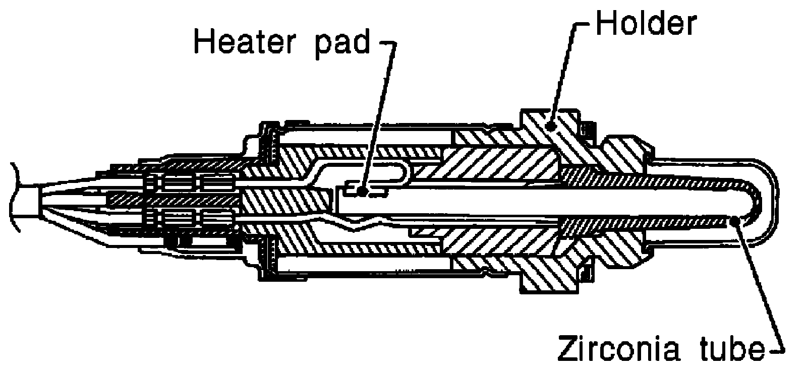
The heated oxygen sensor 2, after three way catalyst (manifold), monitors the oxygen level in the exhaust gas.
Even if switching characteristics of the A/F sensor 1 are shifted, the air-fuel ratio is controlled to stoichiometric, by the signal from the heated oxygen sensor 2.
This sensor is made of ceramic zirconia. The zirconia generates voltage from approximately 1 V in richer conditions to 0 V in leaner conditions.
Under normal conditions the heated oxygen sensor 2 is not used for engine control operation.
On Board Diagnosis Logic
The heated oxygen sensor 2 has a much longer switching time between rich and lean than the air fuel ratio (A/F) sensor 1. The oxygen storage capacity of the three way catalyst (manifold) causes the longer switching time.
MALFUNCTION A
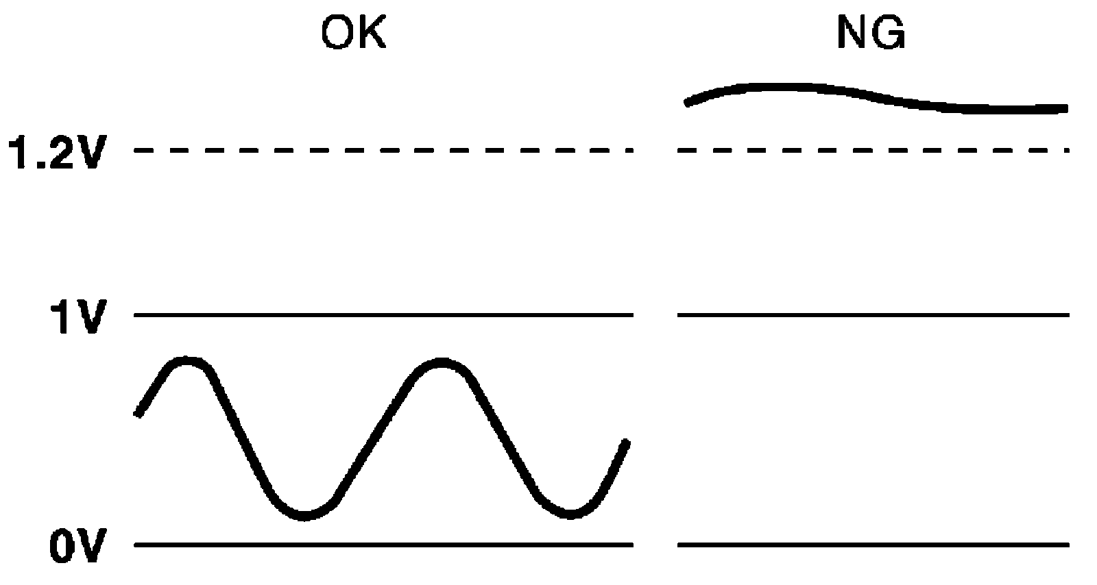
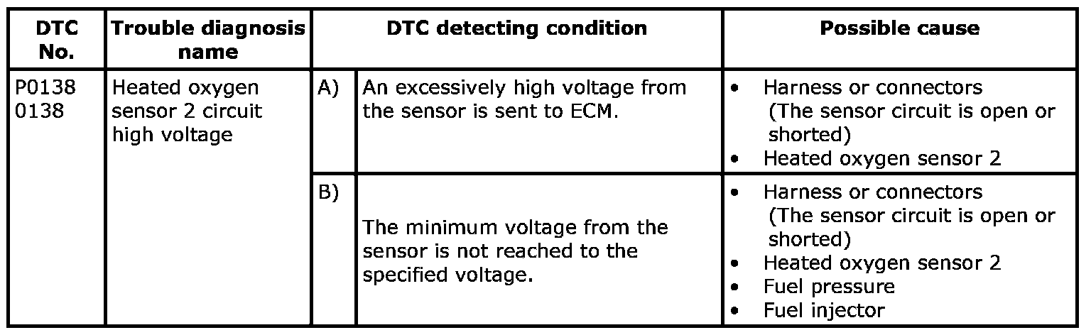
To judge the malfunctions of heated oxygen sensor 2, ECM monitors whether the voltage is unusually high during various driving conditions such as fuel cut.
MALFUNCTION B
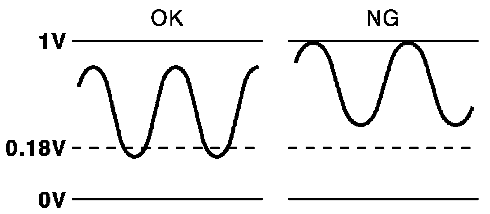
To judge the malfunctions of heated oxygen sensor 2, ECM monitors whether the minimum voltage of sensor is sufficiently low during various driving conditions such as fuel cut.
P0138:
DTC Confirmation Procedure
Perform PROCEDURE FOR MALFUNCTION A first.
If DTC cannot be confirmed, perform PROCEDURE FOR MALFUNCTION B.
NOTE: If DTC Confirmation Procedure has been previously conducted, always turn ignition switch OFF and wait at least 10 seconds before conducting the next test.
PROCEDURE FOR MALFUNCTION A
With SDT
1. Start engine and warm it up to the normal operating temperature.
2. Turn ignition switch OFF and wait at least 10 seconds.
3. Start engine and keep the engine speed between 3,500 and 4,000 rpm for at least 1 minute under no load.
4. Let engine idle for 2 minutes.
5. Check 1st trip DTC.
6. If 1st trip DTC is detected, go to [P0138 HO2S2].
With GST
Follow the procedure "WITH SDT" above.
PROCEDURE FOR MALFUNCTION B
With SDT
TESTING CONDITION: For better results, perform DTC work support at a temperature of 0 to 30 °C (32 to 86 °F).
1. Turn ignition switch ON and select "Data list" mode with SDT.
2. Start engine and warm it up to the normal operating temperature.
3. Turn ignition switch OFF and wait at least 10 seconds.
4. Start engine and keep the engine speed between 3,500 and 4,000 rpm for at least 1 minute under no load.
5. Let engine idle for 1 minute.
6. Make sure that "COOLAN TEMP/S" indicates more than 70 °C (158 °F).
If not, warm up engine and go to next step when "COOLAN TEMP/S" indication reaches 70 °C (158 °F).
7. Open engine hood.
8. Select "HO2S2 (B1) P1146" of "HO2S2" in "DTC work support" mode with SDT.
9. Start engine and following the instruction of SDT display.
NOTE: It will take at most 10 minutes until "COMPLETED" is displayed.
10. Make sure that "OK" is displayed after touching "DTC check".
If "NG" is displayed, refer to [P0138 HO2S2].
If "CAN NOT BE DIAGNOSED" is displayed, perform the following.
a. Turn ignition switch OFF and leave the vehicle in a cool place (soak the vehicle).
b. Return to step 1.
Overall Function Check
Use this procedure to check the overall function of the heated oxygen sensor 2 circuit. During this check, a 1st trip DTC might not be confirmed.
PROCEDURE FOR MALFUNCTION B
With GST
1. Start engine and warm it up to the normal operating temperature.
2. Turn ignition switch OFF and wait at least 10 seconds.
3. Start engine and keep the engine speed between 3,500 and 4,000 rpm for at least 1 minute under no load.
4. Let engine idle for 1 minute.
5. Set voltmeter probes between ECM terminal 74 (HO2S2 signal) and ground.
6. Check the voltage when revving up to 4,000 rpm under no load at least 10 times.

(Depress and release accelerator pedal as soon as possible.)
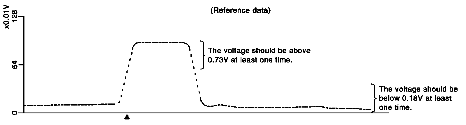
The voltage should be above 0.73 V and below 0.18 V at least once during this procedure.
If the voltage can be confirmed in step 6, step 7 is not necessary.
7. Keep vehicle at idling for 10 minutes, then check the voltage.Or check the voltage when coasting from 80 km/h (50 MPH) in D position (A/T), 4th gear position (M/T). The voltage should be above 0.73 V and below 0.18 V at least once during this procedure.
8. If NG, go to [P0138 HO2S2].
Diagnosis Procedure
PROCEDURE FOR MALFUNCTION A
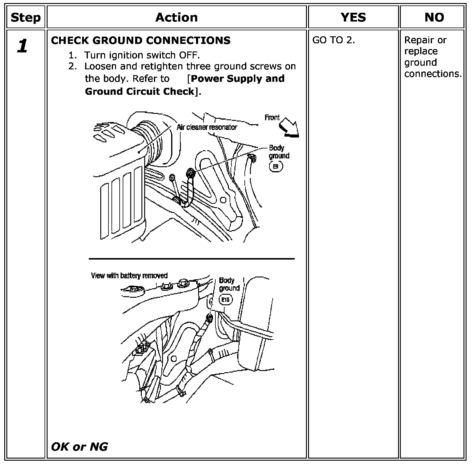
Step 1:
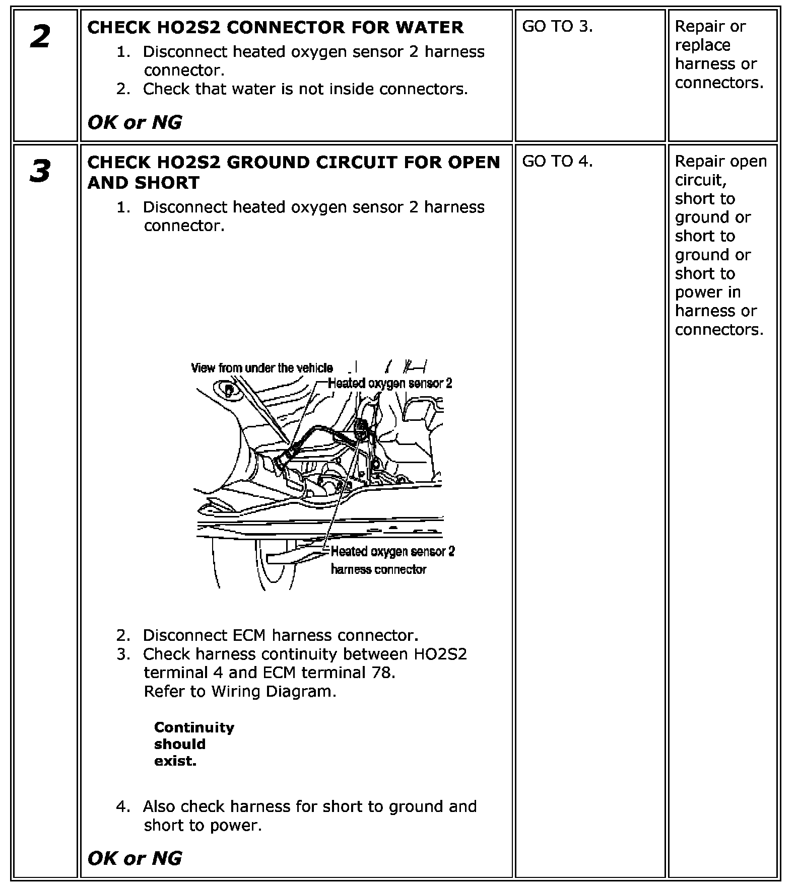
Step 2-3:
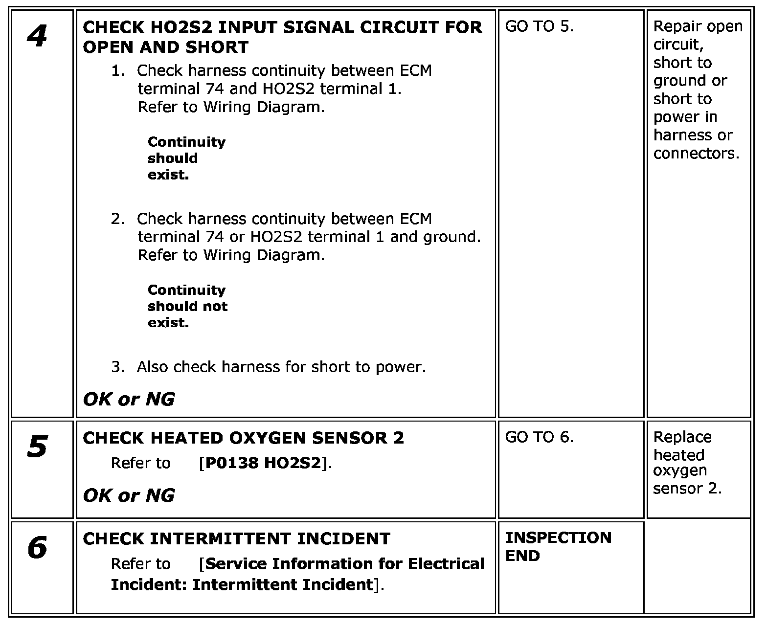
Step 4-6:
PROCEDURE FOR MALFUNCTION B
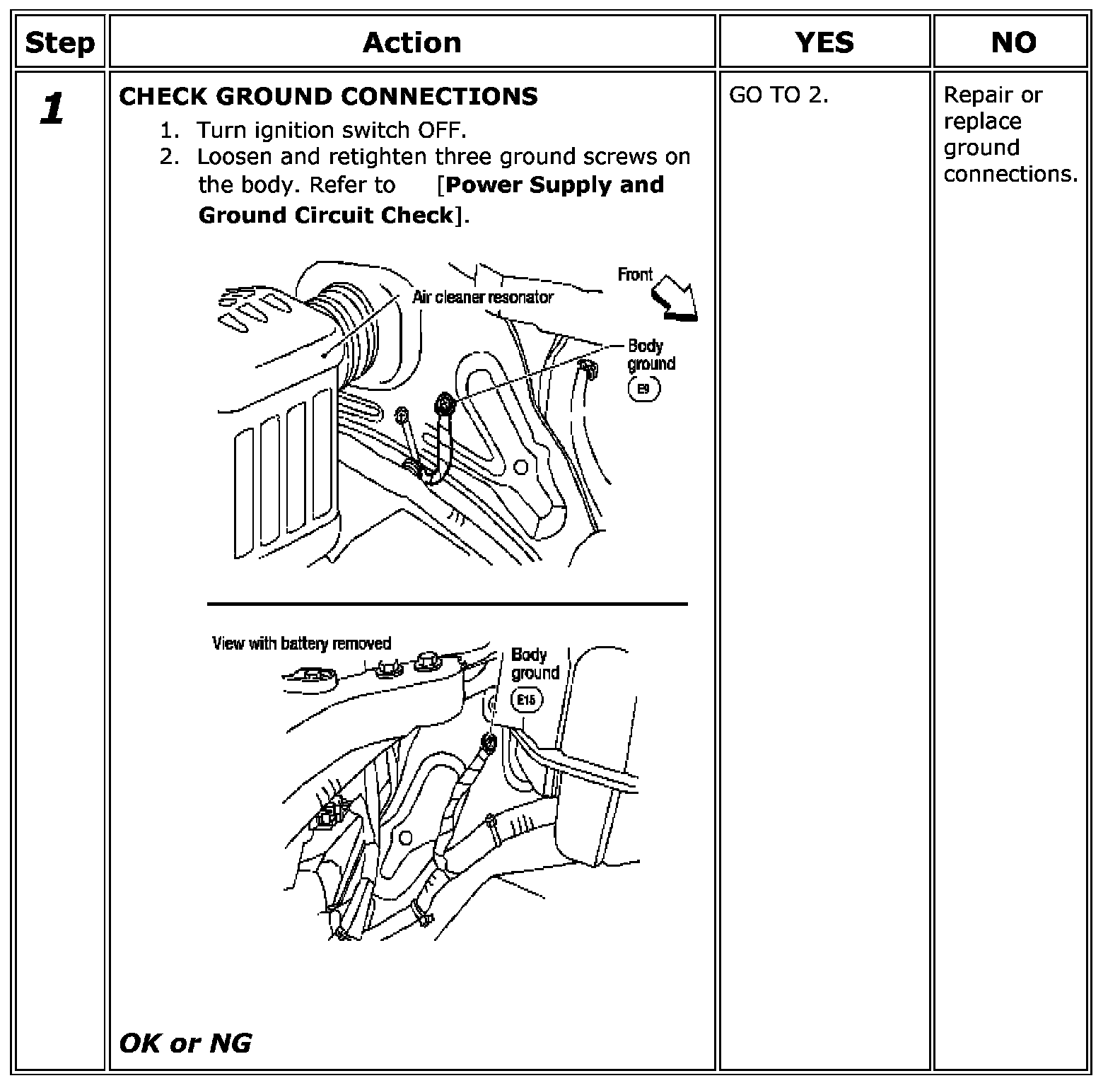
Step 1:
Step 2:
Step 3:
Step 4-6:
Component Inspection
HEATED OXYGEN SENSOR 2
With SDT
1. Turn ignition switch ON and select "Data list" mode with SDT.
2. Start engine and warm it up to the normal operating temperature.
3. Turn ignition switch OFF and wait at least 10 seconds.
4. Start engine and keep the engine speed between 3,500 and 4,000 rpm for at least 1 minute under no load.
5. Let engine idle for 1 minute.
6. Select "FUEL INJECTION" in "Active test" mode, and select "HO2S2 (B1)" as the monitor item with SDT.
7. Check "HO2S2 (B1)" at idle speed when adjusting "FUEL INJECTION" to ±25%.
"HO2S2 (B1)" should be above 0.73 V at least once when the "FUEL INJECTION" is +25%.
"HO2S2 (B1)" should be below 0.18 V at least once when the "FUEL INJECTION" is 25%.
CAUTION:
- Discard any heated oxygen sensor which has been dropped from a height of more than 0.5 m (19.7 in) onto a hard surface such as a concrete floor; use a new one.
- Before installing new oxygen sensor, clean exhaust system threads using Oxygen Sensor Thread Cleaner [commercial service tool (J-43897-18 or J - 43897-12)] and approved anti-seize lubricant (commercial service tool).
Without SDT
1. Start engine and warm it up to the normal operating temperature.
2. Turn ignition switch OFF and wait at least 10 seconds.
3. Start engine and keep the engine speed between 3,500 and 4,000 rpm for at least 1 minute under no load.
4. Let engine idle for 1 minute.
5. Set voltmeter probes between ECM terminal 74 (HO2S2 signal) and ground.
6. Check the voltage when revving up to 4,000 rpm under no load at least 10 times.
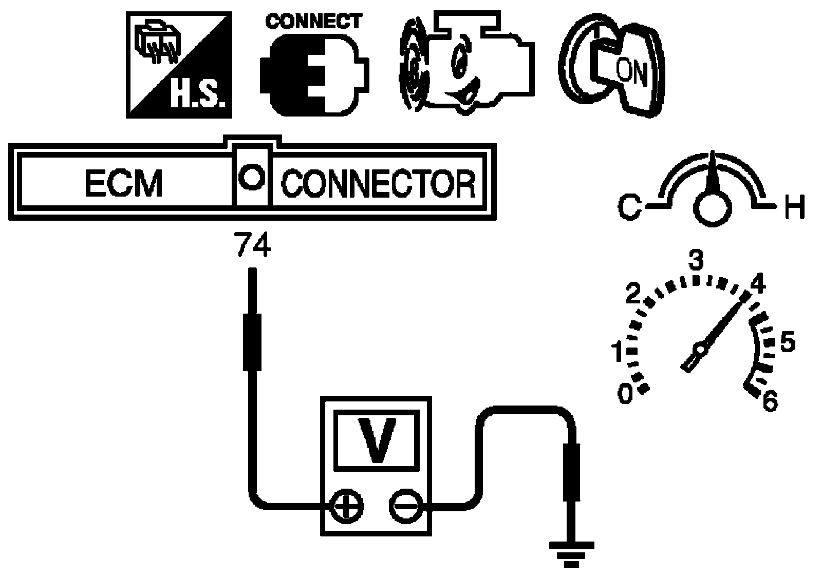
(Depress and release accelerator pedal as soon as possible.)
The voltage should be above 0.73 V and below 0.18 V at least once during this procedure.
If the voltage can be confirmed at step 6, step 7 is not necessary.
7. Keep vehicle at idling for 10 minutes, then check voltage. Or check the voltage when coasting from 80 km/h (50 MPH) in D position with OD "OFF" (A/T), 4th gear position (M/T). The voltage should be above 0.73 V and below 0.18 V at least once during this procedure.
8. If NG, replace heated oxygen sensor 2.
CAUTION:
- Discard any heated oxygen sensor which has been dropped from a height of more than 0.5 m (19.7 in) onto a hard surface such as a concrete floor; use a new one.
- Before installing new oxygen sensor, clean exhaust system threads using Oxygen Sensor Thread Cleaner [commercial service tool (J-43897-18 or J - 43897-12)] and approved anti-seize lubricant (commercial service tool).