P0032
P0031, P0032 A/F Sensor 1 HeaterDescription
SYSTEM DESCRIPTION
System Description:
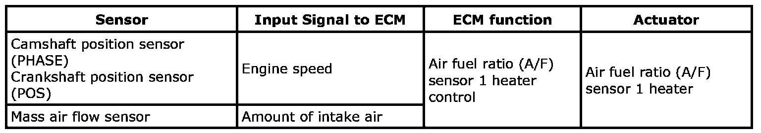
The ECM performs ON/OFF duty control of the A/F sensor 1 heater corresponding to the engine operating condition to keep the temperature of A/F sensor 1 element at the specified range.
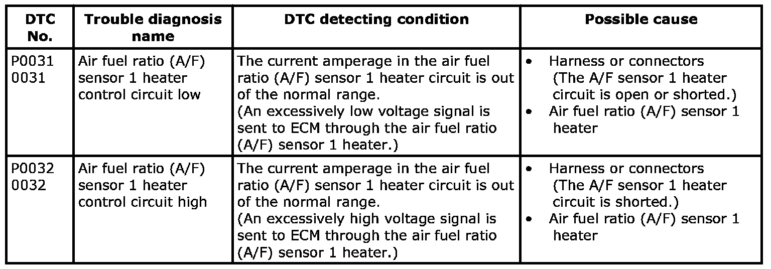
On Board Diagnosis Logic
P0031-P0032:
DTC Confirmation Procedure
NOTE: If DTC Confirmation Procedure has been previously conducted, always turn ignition switch OFF and wait at least 10 seconds before conducting the next test.
TESTING CONDITION:
Before performing the following procedure, confirm that battery voltage is between 10.5 V and 16 V at idle.
WITH SDT
1. Start engine and run it for at least 10 seconds at idle speed.
2. Check 1st trip DTC.
3. If 1st trip DTC is detected, go to [P0031, P0032 A/F Sensor 1 Heater].
WITH GST
Follow the procedure "WITH SDT" above.
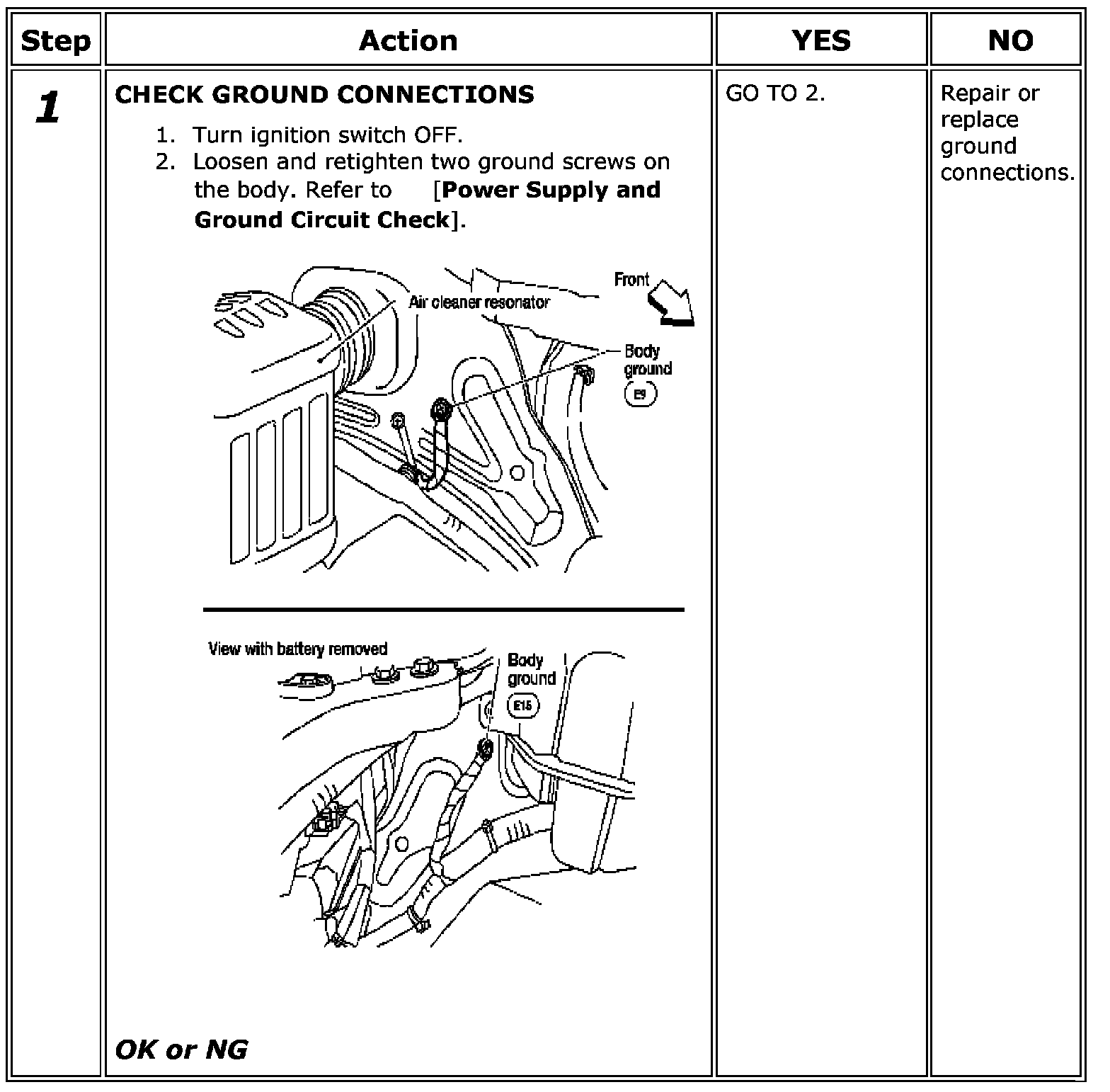
Diagnosis Procedure
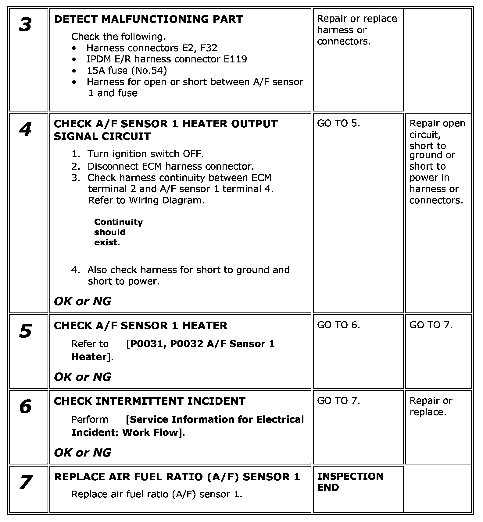
Step 1:
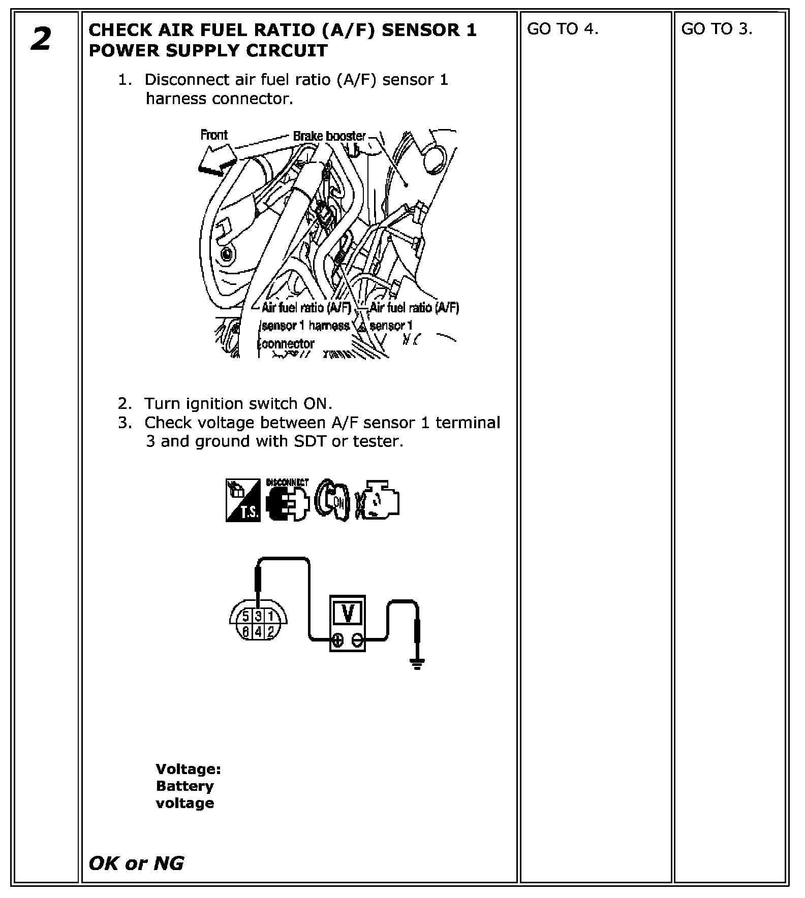
Step 2:
Step 3-7:
Component Inspection
AIR FUEL RATIO (A/F) SENSOR 1 HEATER
Check resistance between terminals 3 and 4.
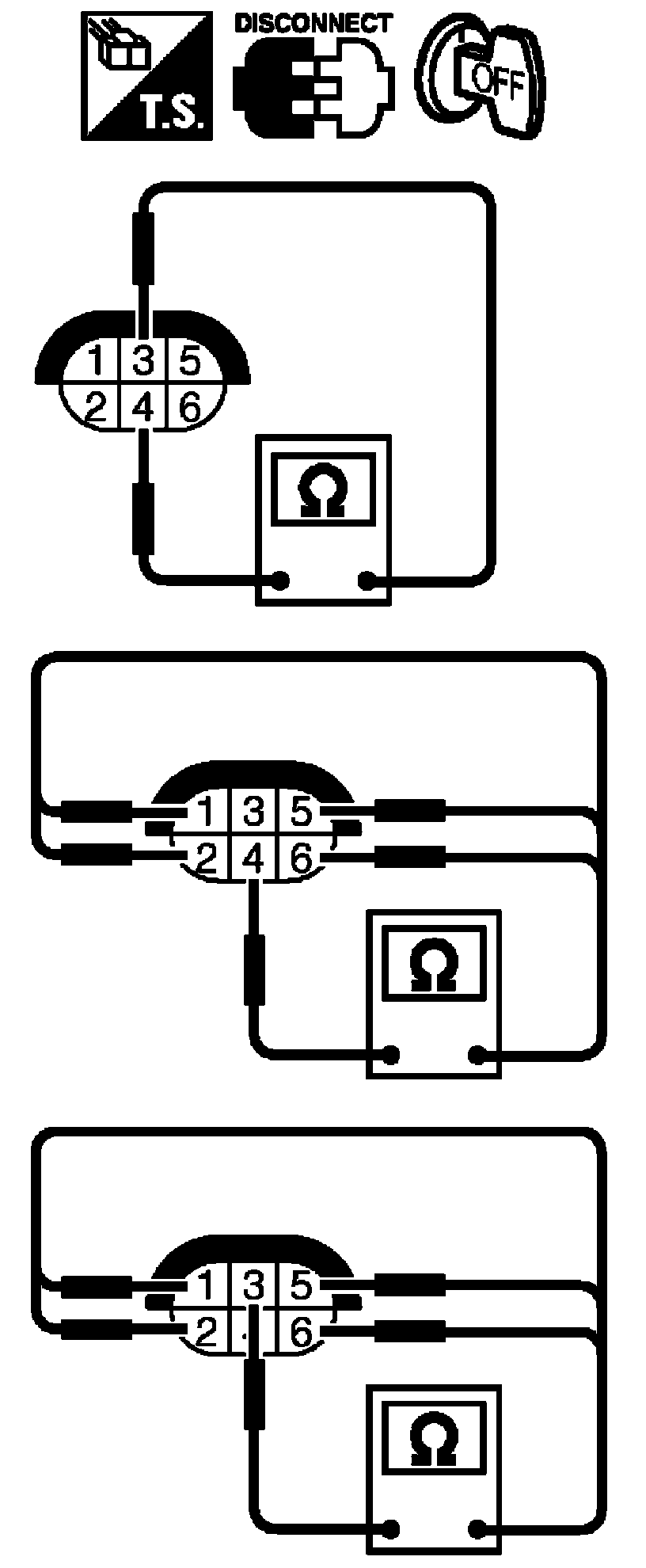
Resistance: 2.3 - 4.3 Ohms [at 25 °C (77 °F)]
Check continuity between terminals 3 and 1, 2, 5, 6, terminals 4 and 1, 2, 5, 6.
Continuity should not exist.
If NG, replace the A/F sensor 1.
CAUTION:
- Discard any A/F sensor which has been dropped from a height of more than 0.5 m (19.7 in) onto a hard surface such as a concrete floor; use a new one.
- Before installing new A/F sensor, clean exhaust system threads using Heated Oxygen Sensor Thread Cleaner [commercial service tool (J-43897-18 or J - 43897-12)] and approved anti-seize lubricant (commercial service tool).