- Liberally lubricate the cylinder walls, piston rings and piston skirts with engine oil.
NOTE:
The piston is directional and must be installed in the engine block in the proper direction.
- Select the correctly numbered piston/connecting rod assembly for the cylinder. A dot (1) showing proper piston orientation is located on the top of the piston.
 Courtesy of SUZUKI OF AMERICA CORP.
NOTE:
If the connecting rod bearings have been used in a running engine, you must replace them with NEW connecting rod bearings for reassembly.
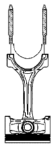
- Install the connecting rod bearing into the connecting rod.
- Install the EN 46121 into the connecting rod bolt holes.
- Compress the piston rings using the J 8037 or equivalent.
 Courtesy of SUZUKI OF AMERICA CORP.
NOTE:
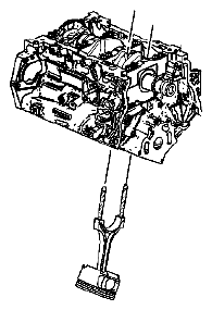
Extreme care must be used when installing the piston and connecting rod in order to be sure the rod does not scrape or nick the cylinder bore, the oil jets, or the crankshaft surfaces.
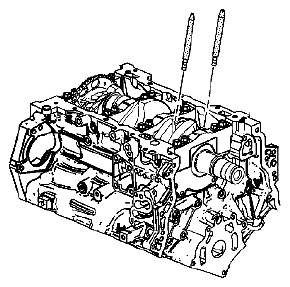
- Using both hands, slowly guide the piston and connecting rod assembly into the cylinder from the top and bottom of the cylinder. DO NOT allow the connecting rod to contact the cylinder wall.
- When the J 8037 contacts the deck surface, gently tap the piston into the cylinder using the handle end of a dead-blow hammer. Guide the connecting rod onto the crankshaft bearing journal using the EN 46121 while gently tapping the piston into the cylinder with a soft-blow hammer.
 Courtesy of SUZUKI OF AMERICA CORP.
- Remove the EN 46121 from the connecting rod bolt holes.