Removal Procedure
 Courtesy of SUZUKI OF AMERICA CORP.
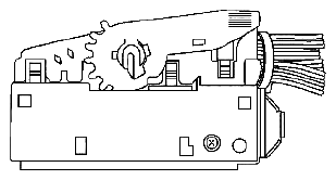
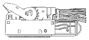
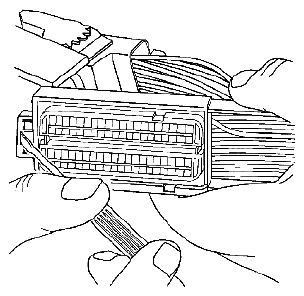
- Locate the assist lever on the top of the connector. Move the assist lever to the forward position.
 Courtesy of SUZUKI OF AMERICA CORP.
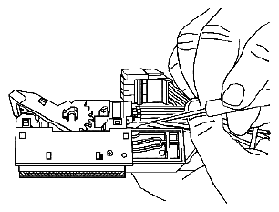
- Disconnect the connector from the component.
 Courtesy of SUZUKI OF AMERICA CORP.
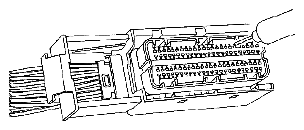
- Locate the dress cover locking tabs at the corners of the connector. Use a small flat-blade tool to release the locking tabs and remove the dress cover.
 Courtesy of SUZUKI OF AMERICA CORP.
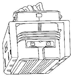
- The terminal positive assurance (TPA) is located in the front of the connector.
 Courtesy of SUZUKI OF AMERICA CORP.
- Use a small flat-blade tool to remove TPA from the connector.
 Courtesy of SUZUKI OF AMERICA CORP.
- Use the J 38125-213 or the J 38125-556 (GM P/N 12093647) tool to release the terminals by inserting the tool into the terminal release cavity. See the release tool cross reference in the Reference Guide of the J-38125 to ensure that the correct release tool is used.
- While holding the removal tool in place, gently pull the wire out of the back of the connector. Always remember never use force when pulling a terminal out of a connector.