Disassembly Procedure
- Remove the front lower control arm assembly. Refer to Control Arm Replacement .
- Note the location of the arrow on the rear bushing relative to the dot stamped on the control arm.
- Note the location of the plus signs on the front bushing relative to the control arm.
 Courtesy of GENERAL MOTORS CORP.
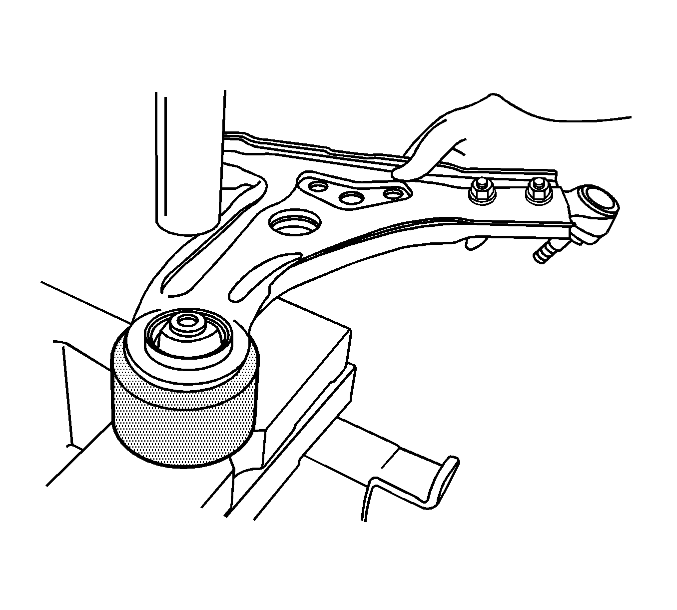
- From the CH-48358
kit, place the CH-48358-2 on a press. See Special Tools .
- Place the control arm assembly on the press. Position the rear bushing on the CH-48358-2.
 Courtesy of GENERAL MOTORS CORP.
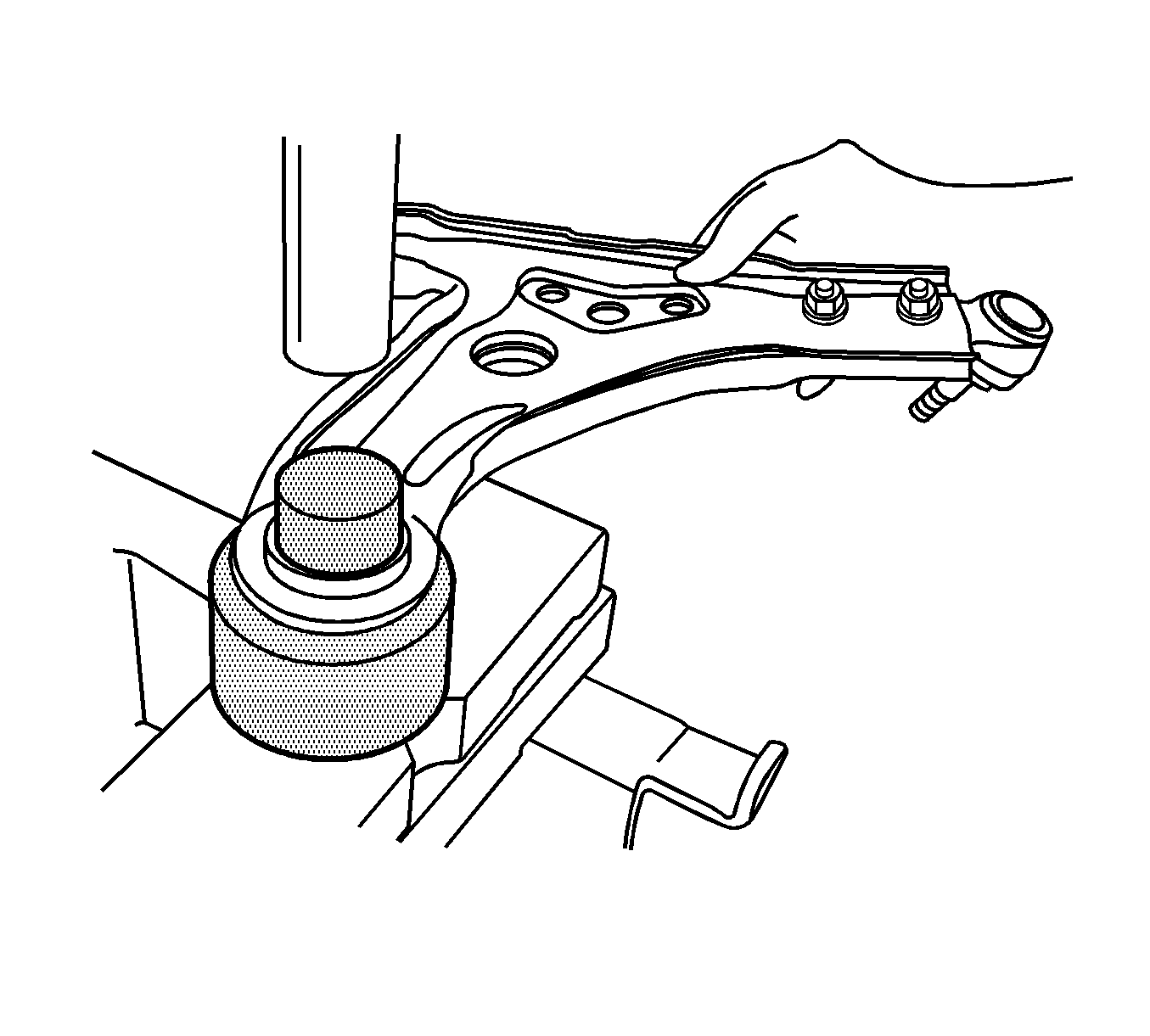
- Place the CH-48358-1 on the front control arm rear bushing.
- Use the press in order to remove the rear bushing.
- Remove any dirt or burrs from the surface of the rear bushing hole.
 Courtesy of GENERAL MOTORS CORP.
- Place the KM-307-B
on a press. See Special Tools .
- From the KM-508-A
kit, place the KM-508-4 (2) on the KM-307-B
. See Special Tools .
- Place the control arm assembly on the press. Position the front control arm front bushing on the KM-508-4.
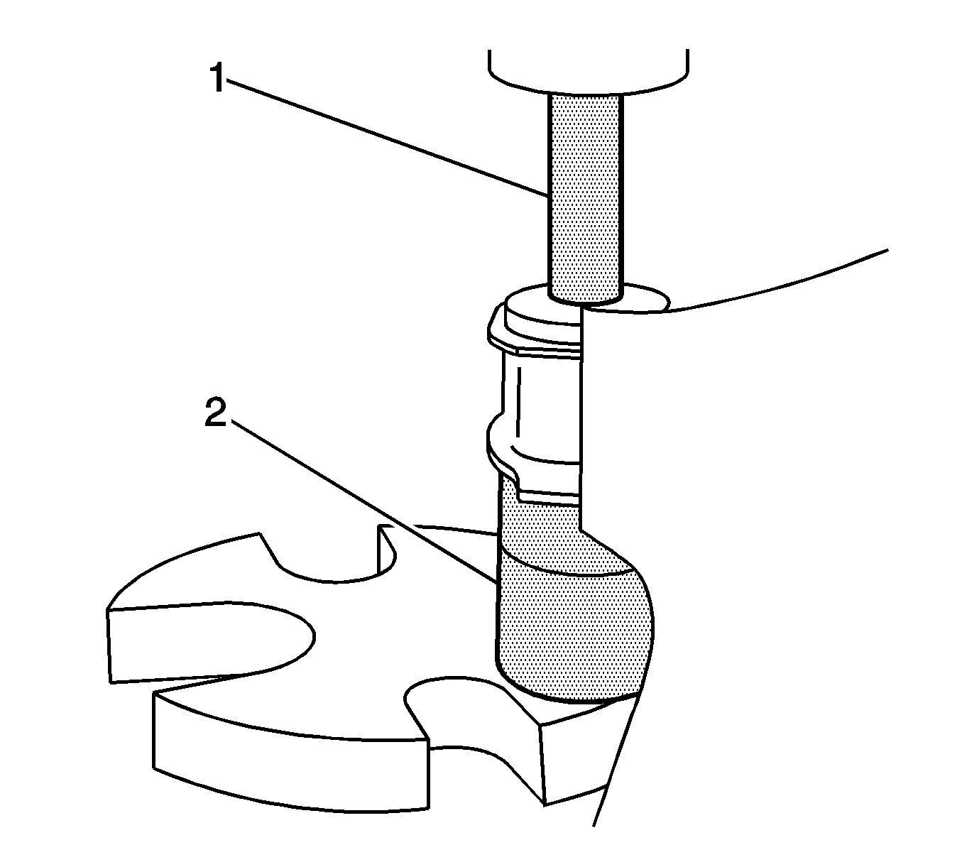
- From the KM-158
kit, place the KM-158-5 (1) on the front bushing. See Special Tools .
- Use the press in order to remove the front bushing.