| 1 |
DTC Check
- Turn ignition switch to OFF position.
- Connect scan tool to DLC.
- Check DTC in the following control modules.
- ECM
- TCM
- ABS/ESP® control module
- BCM
- Combination meter
- Keyless start control module
- 4WD control module
Is there any DTC other than CAN-DTC?
|
Go to applicable troubleshooting of DTC other than CAN-DTC. |
Go to Step 2. |
| 2 |
Control module connector check
- Turn ignition switch to OFF position.
- Be sure to disconnect scan tool from DLC.
- Disconnect all the following control module/sensor connectors.
- Control modules communicated by CAN
- ECM
- TCM
- ABS/ESP® control module
- BCM
- Combination meter
- Keyless start control module
- 4WD control module
- ID controller (Canada model)
- Sensors communicated by CAN
- Steering angle sensor (ESP® model)
- Yaw rate/G sensor assembly (ESP® model)
- Check for proper connection to terminal of each CAN line of all control module (communicated by CAN) connectors.
- If OK, connect all connectors of control module/sensor communicated by CAN securely.
- Recheck DTC for all control modules communicated by CAN.
Is there any CAN-DTC?
|
Go to Step 3. |
Intermittent trouble. Check for intermittent referring to INTERMITTENT AND POOR CONNECTION INSPECTION
. |
| 3 |
CAN line check
- Turn ignition switch to OFF position.
- Disconnect connectors of all control module/sensor communicated by CAN.
- Check all the following CAN lines for open, short to power circuit, short to ground circuit, short to other CAN line and high resistance.
- Between BCM connector and DLC
- Between BCM connector and ABS/ESP® control module connector
- Between ABS/ESP® control module connector and ECM connector
- Between ECM connector and TCM connector
- Between BCM connector and keyless start control module connector
- Between BCM connector and yaw rate/G sensor connector
- Between BCM connector and ID controller connector
- Between combination meter connector and 4WD control module connector
- Between BCM connector and combination meter connector
- Between combination meter connector and steering angle sensor connector
Are all CAN lines in good condition?
|
Go to Step 4. |
Repair CAN line. |
| 4 |
Power and ground circuits check of BCM, ECM, ABS/ESP® control module and combination meter
- Check power and ground circuits the following control module.
Are they in good condition?
|
Go to Step 5. |
Repair power and/or ground circuit. |
| 5 |
CAN communication check of BCM, ECM, ABS/ESP® control module and combination meter
- Turn ignition switch to OFF position.
- Connect BCM, ECM, ABS/ESP® control module and combination meter connectors.
- Perform "Communication Bus Check" under "Bus Check" using SUZUKI-SDT with ignition switch turned ON.
Are all of BCM, ECM, ABS/ESP® control module and combination meter normally displayed?
|
Go to Step 12. |
Go to Step 6. |
| 6 |
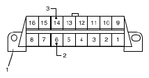
Terminating resistance check in ECM and combination meter
- Turn ignition switch to OFF position and then disconnect negative (-) cable at battery.
- Measure resistance between CAN High terminal (2) and CAN Low terminal (3) on DLC (1).
 Courtesy of SUZUKI OF AMERICA CORP. Courtesy of SUZUKI OF AMERICA CORP.
If resistance 57 - 67 Ω?
|
Go to Step 7. |
Go to Step 8. |
| 7 |
Substitute ECM and recheck
- Substitute a known-good ECM and recheck.
Is it in good condition?
|
End. |
Substitute a known-good combination meter and recheck. If NG, go to Step 11. |
| 8 |
Terminating resistance check in ECM
- Make sure that ignition switch is OFF position and battery negative (-) cable is disconnected.
- Disconnect combination meter connector.
- Measure resistance between CAN high terminal and CAN low terminal on DLC as the same manner as Step 6.
Is resistance 114 - 134 Ω?
|
Substitute a known-good combination meter. |
Go to Step 9. |
| 9 |
Internal circuit check in BCM
- Make sure that ignition switch is OFF position and battery negative (-) cable is disconnected.
- Disconnect ABS/ESP® control module connector.
- Measure resistance between the followings
- Between CAN high terminal on DLC and "E08-2" terminal on ABS/ESP® control module connector
- Between CAN low terminal on DLC and "E08-13" terminal on ABS/ESP® control module connector
Is each resistance 0 - 1 Ω?
|
Go to Step 10. |
Substitute a known-good BCM. |
| 10 |
Internal circuit check in ABS/ESP® control module
- Make sure that ignition switch is OFF position and battery negative (-) cable is disconnected.
- Connect ABS/ESP® control module connector and disconnect ECM connector.
- Measure resistance between the followings
- Between CAN High terminal on DLC and "E01-4" terminal on ECM connector
- Between CAN Low terminal on DLC and "E01-19" terminal on ECM connector
If each resistance 0 - 1 Ω?
|
Substitute a known-good ECM and recheck. If NG, go to step 11. |
Substitute a known-good ABS/ESP® control module. |
| 11 |
Substitute BCM and recheck
- Substitute a known-good BCM and recheck.
Is it in good condition?
|
End. |
Substitute a known-good ABS/ESP® control module. |
| 12 |
CAN communication check of TCM
- Turn ignition switch to OFF position.
- Connect TCM connectors.
- Perform "Communication Bus Check" under "Bus Check" using SUZUKI-SDT with ignition switch turned ON.
Are all of BCM, ECM, ABS/ESP® control module, combination meter and TCM normally displayed?
|
Go to Step 13. |
Check power and ground circuits of TCM referring to TCM POWER AND GROUND CIRCUIT CHECK
. If OK, substitute a known-good TCM. |
| 13 |
CAN communication check of keyless start control module
- Turn ignition switch to OFF position.
- Connect keyless start control module connector.
- Perform "Communication Bus Check" under "Bus Check" using SUZUKI-SDT with ignition switch turned ON.
Are all of BCM, ECM, ABS/ESP® control module, combination meter, TCM and keyless start control module normally displayed?
|
Go to Step 14. |
Check power and ground circuits of keyless start control module referring to KEYLESS START CONTROL MODULE POWER AND GROUND CIRCUIT CHECK
. If OK, substitute a known-good keyless start control module. |
| 14 |
CAN communication check of Yaw rate/G sensor assembly (ESP® model)
- Turn ignition switch to OFF position.
- Connect Yaw rate/G sensor assembly connector.
- Perform "Communication Bus Check" under "Bus Check" using SUZUKI-SDT with ignition switch turned ON.
Are all of BCM, ECM, ABS/ESP® control module, combination meter, TCM, keyless start control module and Yaw rate/G sensor assembly normally displayed?
|
Go to Step 15. |
Check power and ground circuit of Yaw rate/G sensor assembly referring to "Step 3" to "Step 5" under DTC C1034/C1039: YAW RATE/G SENSOR ASSEMBLY POWER SUPPLY FAILURE/INTERNAL FAILURE
. If OK, substitute a known-good Yaw rate/G sensor assembly. |
| 15 |
CAN communication check of ID controller (Canada model)
- Turn ignition switch to OFF position.
- Connect combination meter connector and ID controller.
- Perform "Communication Bus Check" under "Bus Check" on SUZUKI-SDT with ignition switch turned ON.
Are all of BCM, ECM, ABS/ESP® control module, combination meter, TCM, keyless start control module, Yaw rate/G sensor assembly, combination meter and ID controller normally displayed?
|
Go to Step 16. |
Check power and ground circuits of ID controller. If OK, substitute a known-good ID controller. |
| 16 |
CAN communication check of 4WD control module
- Turn ignition switch to OFF position.
- Connect combination meter connector and 4WD control module.
- Perform "Communication Bus Check" under "Bus Check" on SUZUKI-SDT with ignition switch turned ON.
Are all of BCM, ECM, ABS/ESP® control module, combination meter, TCM, keyless start control module, Yaw rate/G sensor assembly, combination meter, ID controller and 4WD control module normally displayed?
|
Go to Step 17. |
Check power and ground circuits of 4WD control module referring to "Step 2" and "Step 3" under DTC C1240: 4WD CONTROL MODULE POWER SUPPLY CIRCUIT MALFUNCTION
. If OK, substitute a known-good 4WD control module. |
| 17 |
CAN communication check of steering angle sensor (ESP® model)
- Turn ignition switch to OFF position.
- Connect steering angle sensor.
- Perform "Communication Bus Check" under "Bus Check" using SUZUKI-SDT with ignition switch turned ON.
Are all of BCM, ECM, ABS/ESP® control module, combination meter, TCM, keyless start control module, Yaw rate/G sensor assembly, combination meter, ID controller, 4WD control module and steering angle sensor normally displayed?
|
Recheck DTC. |
Check power and ground circuit of steering angle sensor referring to "Step 4" and "Step 5" under DTC C1037: STEERING ANGLE SENSOR POWER SUPPLY FAILURE
. If OK, substitute a known-good Yaw rate/G sensor assembly. |