Mainshaft Disassembly and Assembly: Assembly
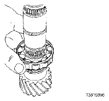
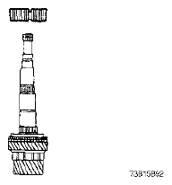
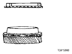
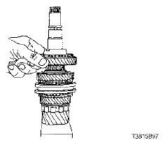
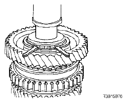
- Install the mainshaft bearing.
 Courtesy of SUZUKI OF AMERICA CORP.
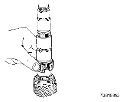
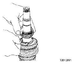
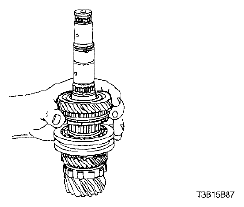
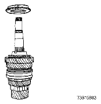
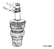
- Install the ring, the thrust washer, and the 4th-gear needle bearing.
 Courtesy of SUZUKI OF AMERICA CORP.
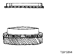
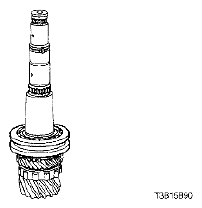
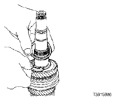
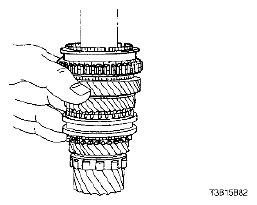
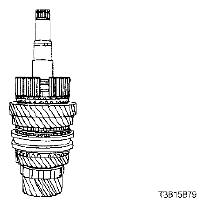
- Attach the synchronizer blocking ring to the 4th gear.
 Courtesy of SUZUKI OF AMERICA CORP.
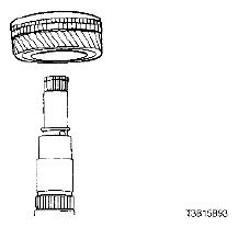
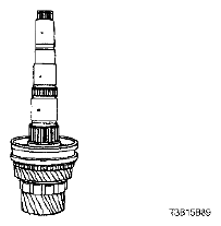
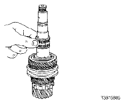
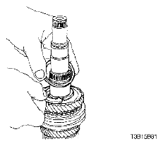
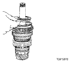
- Install the 4th-gear assembly.
 Courtesy of SUZUKI OF AMERICA CORP.
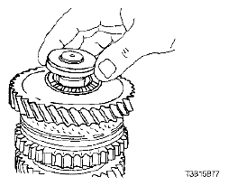
- Install the 3rd -- 4th gear synchronizer containing the synchronizer spring.
 Courtesy of SUZUKI OF AMERICA CORP.
- Install the snap ring and the washer around the mainshaft.
 Courtesy of SUZUKI OF AMERICA CORP.
- Install the synchronizer sleeve containing the keys and the spring.
 Courtesy of SUZUKI OF AMERICA CORP.
- Install the 3rd-gear needle bearing.
 Courtesy of SUZUKI OF AMERICA CORP.
- Attach the synchronizer blocking ring to the 3rd gear.
 Courtesy of SUZUKI OF AMERICA CORP.
- Install the 3rd-gear assembly.
 Courtesy of SUZUKI OF AMERICA CORP.
- Install the thrust washer and the ring.
 Courtesy of SUZUKI OF AMERICA CORP.
- Install the 2nd-gear needle bearing.
 Courtesy of SUZUKI OF AMERICA CORP.
- Install the 2nd gear.
 Courtesy of SUZUKI OF AMERICA CORP.
- Install the 1st - 2nd gear blocking ring.
 Courtesy of SUZUKI OF AMERICA CORP.
- Install the 1st - 2nd synchronizer gear.
 Courtesy of SUZUKI OF AMERICA CORP.
- Install the washer and the snap ring.
 Courtesy of SUZUKI OF AMERICA CORP.
- Install the 1st-gear needle bearing.
 Courtesy of SUZUKI OF AMERICA CORP.
- Install the keys onto the 1st - 2nd synchronizer gear.
 Courtesy of SUZUKI OF AMERICA CORP.
- Install the synchronizer hub sleeve containing the synchronizer spring.
 Courtesy of SUZUKI OF AMERICA CORP.
- Install the outer blocking ring.
- Install the mainshaft wear plate, the flat-type 1st gear needle bearing, and the 1st gear.
 Courtesy of SUZUKI OF AMERICA CORP.
- Install the snap ring.
 Courtesy of SUZUKI OF AMERICA CORP.
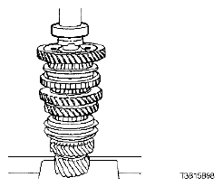
- Press on the mainshaft bearing.
 Courtesy of SUZUKI OF AMERICA CORP.