Differential Disassembly and Assembly: Disassembly
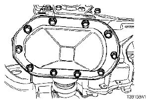
- Remove the differential cover bolts, the differential cover, and the differential cover gasket.
 Courtesy of SUZUKI OF AMERICA CORP.
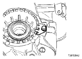
- Remove the bearing-adjusting ring retainer plate bolt and the bearing-adjusting ring retainer plate.
 Courtesy of SUZUKI OF AMERICA CORP.
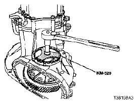
- Remove the bearing-adjusting ring using the remover/installer KM-520.
 Courtesy of SUZUKI OF AMERICA CORP.
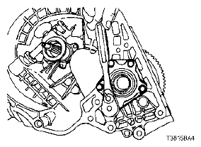
- Remove the right-side bearing-retainer bolts and the right-side bearing retainer.
 Courtesy of SUZUKI OF AMERICA CORP.
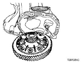
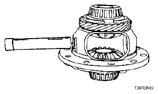
- Remove the differential assembly from the transaxle case.
 Courtesy of SUZUKI OF AMERICA CORP.
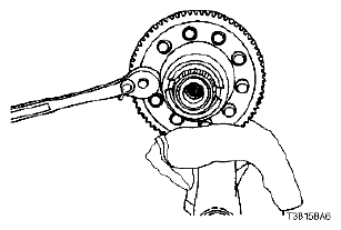
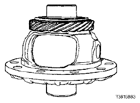
- Remove the ring gear bolts.
 Courtesy of SUZUKI OF AMERICA CORP.
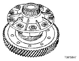
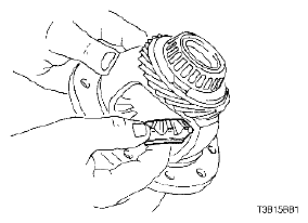
- Separate the ring gear from the differential housing.
 Courtesy of SUZUKI OF AMERICA CORP.
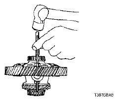
- Drive the pinion gear shaft lock pin from the differential housing and the pinion gear shaft.
 Courtesy of SUZUKI OF AMERICA CORP.
- Remove the pinion gear shaft.
 Courtesy of SUZUKI OF AMERICA CORP.
- Remove the pinion gears and the washers.
- Remove the side gears and the side thrust washers.
 Courtesy of SUZUKI OF AMERICA CORP.
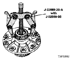
- Remove both of the differential bearings using the bearing puller J-22888-20-A with the puller legs J-22888-35.
 Courtesy of SUZUKI OF AMERICA CORP.
- Remove the speedometer drive gear from the differential gear housing.
 Courtesy of SUZUKI OF AMERICA CORP.