Major Component Assy Disassembly: Disassembly
- Remove the transaxle from the vehicle. Refer to Transaxle Assembly Removal and Installation
.
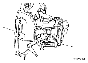
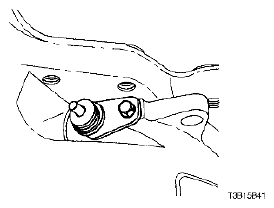
- Remove the filler plug at the cover.
 Courtesy of SUZUKI OF AMERICA CORP.
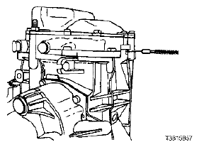
- Remove the bolts from the gearshift lever cover.
 Courtesy of SUZUKI OF AMERICA CORP.
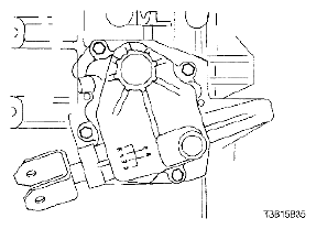
- Remove the gearshift lever cover.
- Remove the gearshift cover gasket.
 Courtesy of SUZUKI OF AMERICA CORP.
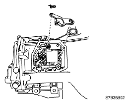
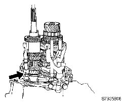
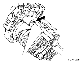
- Remove the reverse lever clip.
- Remove the reverse assist lever.
 Courtesy of SUZUKI OF AMERICA CORP.
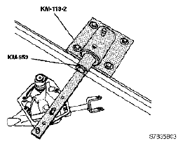
- Bolt the gearshift lever cover to the fixture KM-552.
- Position the fixture KM-552 into the base KM-113-2.
 Courtesy of SUZUKI OF AMERICA CORP.
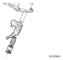
- Remove the snap ring, the bushing, the spring, and the intermediate lever.
 Courtesy of SUZUKI OF AMERICA CORP.
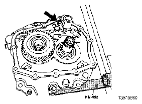
- Remove the shift finger lever pin.
 Courtesy of SUZUKI OF AMERICA CORP.
- Remove the gearshift rod and the shift finger lever.
 Courtesy of SUZUKI OF AMERICA CORP.
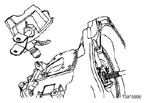
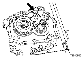
- Remove the bolt and the speedometer-driven gear from the transaxle housing.
 Courtesy of SUZUKI OF AMERICA CORP.
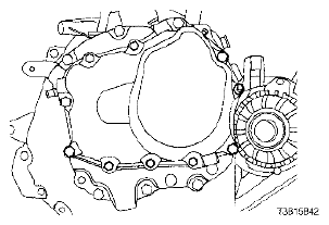
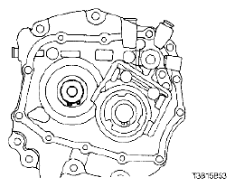
- Remove the transaxle cover bolts.
 Courtesy of SUZUKI OF AMERICA CORP.
- Remove the transaxle cover.
 Courtesy of SUZUKI OF AMERICA CORP.
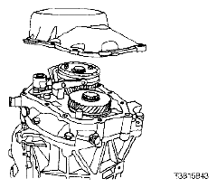
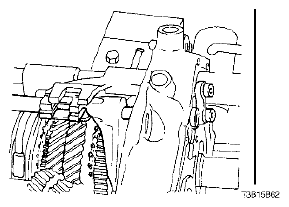
- Shift the transaxle into 2nd gear.
- Remove the bearing plate bolts.
 Courtesy of SUZUKI OF AMERICA CORP.
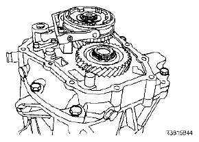
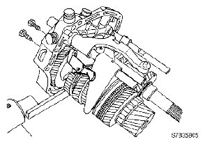
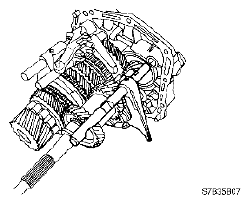
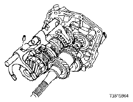
- Remove the bearing plate from the case with the shafts attached.
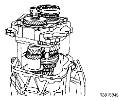 Courtesy of SUZUKI OF AMERICA CORP.
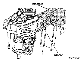
- Shift the transaxle into reverse (R).
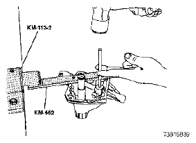
- Bolt the bearing plate to the fixture KM-552 and install the fixture KM-552 into the base KM-113-2.
 Courtesy of SUZUKI OF AMERICA CORP.
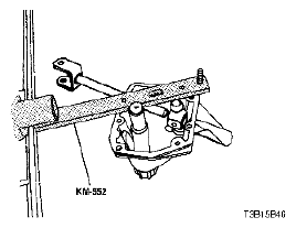
- Remove the bolts and the 5th-gear fork from the bearing plate.
 Courtesy of SUZUKI OF AMERICA CORP.
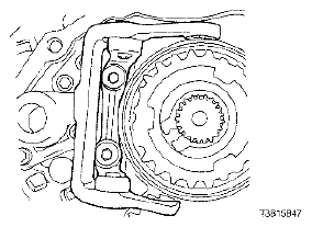
- Remove the mainshaft-driven 5th-speed assembly snap ring.
 Courtesy of SUZUKI OF AMERICA CORP.
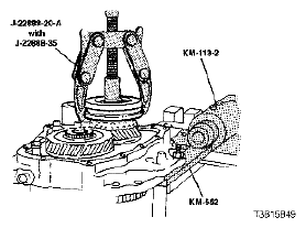
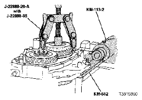
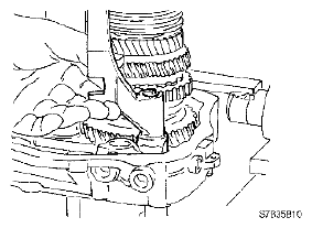
- Remove the 5th driven gear synchronizer sleeve and the synchronizer gear using the bearing puller J-22888-20-A with the puller legs J-22888-35.
 Courtesy of SUZUKI OF AMERICA CORP.
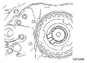
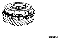
- Remove the mainshaft-driven 5th-gear assembly.
 Courtesy of SUZUKI OF AMERICA CORP.
- Remove the brass synchronizer ring.
 Courtesy of SUZUKI OF AMERICA CORP.
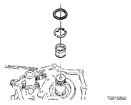
- Remove the needle bearing, the retaining ring, and the thrust washers.
 Courtesy of SUZUKI OF AMERICA CORP.
- Remove the input drive 5th-gear snap ring.
 Courtesy of SUZUKI OF AMERICA CORP.
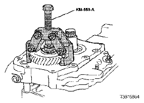
- Remove the input drive 5th gear using the 5th-gear puller KM-553-A.
 Courtesy of SUZUKI OF AMERICA CORP.
- Remove the bolts and the 5th-gearshift connector from the bearing plate using the pawl.
 Courtesy of SUZUKI OF AMERICA CORP.
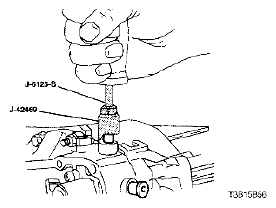
- Remove the four shift-rod plugs using the shift rod remover J-42469 and the slide hammer J-6125-B.
 Courtesy of SUZUKI OF AMERICA CORP.
- Remove the spring and the rod lock pin from the small plug hole.
 Courtesy of SUZUKI OF AMERICA CORP.
- Remove the pin from the reverse gearshift rod/fork assembly.
 Courtesy of SUZUKI OF AMERICA CORP.
- Remove the reverse gearshift rod/fork assembly from the bearing plate.
 Courtesy of SUZUKI OF AMERICA CORP.
- Remove the bolts from the support bracket.
 Courtesy of SUZUKI OF AMERICA CORP.
- Remove the 1st -- 2nd gearshift fork holding pin.
 Courtesy of SUZUKI OF AMERICA CORP.
- Drive the 1st -- 2nd gearshift rod out until it is just free of the bearing plate.
 Courtesy of SUZUKI OF AMERICA CORP.
- Remove the support bracket from the bearing plate.
 Courtesy of SUZUKI OF AMERICA CORP.
- Remove the 3rd -- 4th gearshift fork holding pin and the 3rd -- 4th gearshift rod.
 Courtesy of SUZUKI OF AMERICA CORP.
- Remove the 5th gearshift lever from the bearing plate.
 Courtesy of SUZUKI OF AMERICA CORP.
- Remove the 1st -- 2nd gearshift rod.
 Courtesy of SUZUKI OF AMERICA CORP.
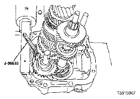
- Compress the snap ring holding the mainshaft and secure it with the snap ring retainer J-36633.
 Courtesy of SUZUKI OF AMERICA CORP.
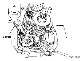
- Hold the snap ring open at the base of the input shaft using the snap ring pliers.
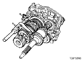
- Remove the mainshaft assembly and the input shaft assembly from the bearing plate.
 Courtesy of SUZUKI OF AMERICA CORP.