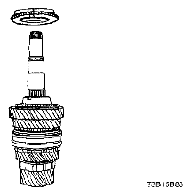
Mainshaft Disassembly and Assembly: Disassembly
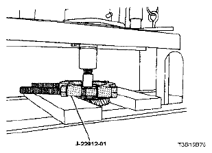
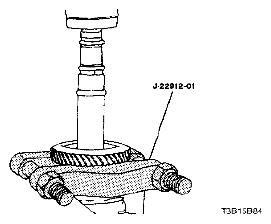
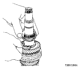
- Remove the mainshaft bearing using the universal bearing puller J-22912-01.
 Courtesy of SUZUKI OF AMERICA CORP.
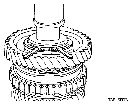
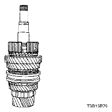
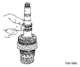
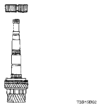
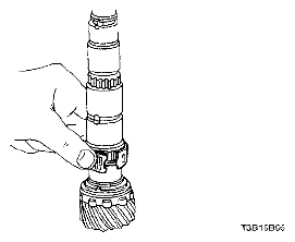
- Remove the snap ring.
 Courtesy of SUZUKI OF AMERICA CORP.
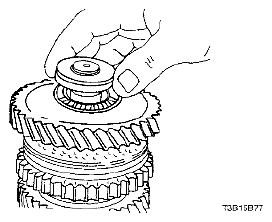
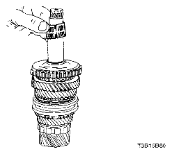
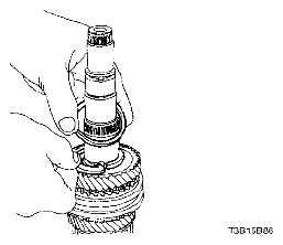
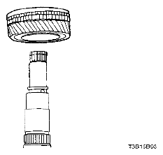
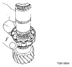
- Remove the 1st gear, the flat-type 1st-gear needle bearing, and the mainshaft wear plate.
 Courtesy of SUZUKI OF AMERICA CORP.
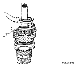
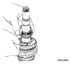
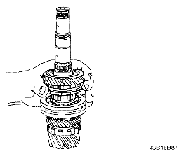
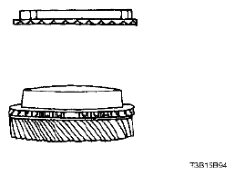
- Remove the synchronizer hub sleeve that contains the synchronizer spring.
- Remove the outer blocking ring.
 Courtesy of SUZUKI OF AMERICA CORP.
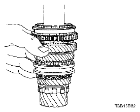
- Remove the keys from the 1st - 2nd synchronizer gear.
 Courtesy of SUZUKI OF AMERICA CORP.
- Remove the barrel-type 1st-gear needle bearing.
 Courtesy of SUZUKI OF AMERICA CORP.
- Remove the snap ring and the washer.
 Courtesy of SUZUKI OF AMERICA CORP.
- Remove the 1st - 2nd synchronizer gear from the mainshaft.
 Courtesy of SUZUKI OF AMERICA CORP.
- Remove the 1st - 2nd gear blocking ring.
 Courtesy of SUZUKI OF AMERICA CORP.
- Remove the 2nd gear using the universal bearing puller J-22912-01.
 Courtesy of SUZUKI OF AMERICA CORP.
- Remove the 2nd-gear needle bearing.
 Courtesy of SUZUKI OF AMERICA CORP.
- Remove the ring and the thrust washer.
 Courtesy of SUZUKI OF AMERICA CORP.
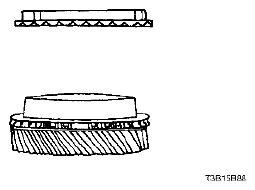
- Remove the 3rd gear and the synchronizer blocking ring.
 Courtesy of SUZUKI OF AMERICA CORP.
- Separate the synchronizer blocking ring from the 3rd gear.
 Courtesy of SUZUKI OF AMERICA CORP.
- Remove the 3rd-gear needle bearing from the mainshaft.
 Courtesy of SUZUKI OF AMERICA CORP.
- Remove the synchronizer sleeve containing the keys and the spring.
 Courtesy of SUZUKI OF AMERICA CORP.
- Remove the snap ring and the washer from the mainshaft.
 Courtesy of SUZUKI OF AMERICA CORP.
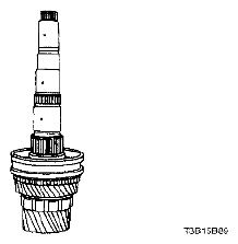
- Remove the 3rd - 4th synchronizer gear containing the synchronizer spring.
 Courtesy of SUZUKI OF AMERICA CORP.
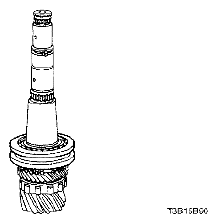
- Remove the 4th-gear assembly.
 Courtesy of SUZUKI OF AMERICA CORP.
- Separate the synchronizer blocking ring from the 4th gear.
 Courtesy of SUZUKI OF AMERICA CORP.
- Remove the 4th-gear needle bearing, the ring, and the thrust washer.
 Courtesy of SUZUKI OF AMERICA CORP.
- Remove the mainshaft bearing.
 Courtesy of SUZUKI OF AMERICA CORP.