| 1 |
Scan tool check
- Disconnect scan tool from DLC with ignition switch turned OFF.
- Check for proper connection to all terminals of scan tool connector.
- If OK, connect scan tool to another vehicle of this type with ignition switch turned OFF.
- Check communication between scan tool and ECM by DTC check in ECM.
Is it possible to check DTC in ECM? |
Go to Step 2. |
Scan tool faulty. Refer to its operator's manual. |
| 2 |
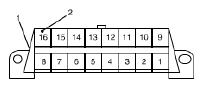
DLC power circuit check
- Check for proper connection to all DLC (1) terminals with ignition switch turned OFF.
- If OK, measure voltage between +B terminal (2) of DLC and vehicle body ground with ignition switch turned to ON position.
 Courtesy of SUZUKI OF AMERICA CORP. Courtesy of SUZUKI OF AMERICA CORP.
Is voltage 10 - 14 V? |
Go to Step 3. |
Repair power circuit. |
| 3 |
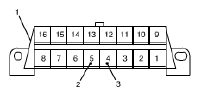
DLC ground circuit check
- Ignition switch turn to OFF position.
- Check DLC (1) ground circuits as follows.
- Measure resistance between signal ground terminal (2) of DLC and vehicle body ground.
- Measure resistance between body ground terminal (3) of DLC and vehicle body ground.
 Courtesy of SUZUKI OF AMERICA CORP. Courtesy of SUZUKI OF AMERICA CORP.
Is resistance 1 Ω or less? |
Go to Step 4. |
Repair ground circuit(s). |
| 4 |
DTC Check
- Turn ignition switch to OFF position.
- Connect scan tool to DLC.
- Check DTC in the following control modules that communicate with scan tool by K-line.
- ABS/ESP® control module
- BCM
- Combination meter
- Keyless start control module
- 4WD control module
Is there any DTC other than CAN-DTC? |
Go to applicable troubleshooting of DTC other than CAN-DTC. |
Go to Step 5. |
| 5 |
CAN line check between DLC and BCM
- Turn ignition switch to OFF position.
- Disconnect BCM connector from BCM.
- Check for proper connection to all terminals of BCM connector.
- If OK, check CAN lines between DLC and BCM connector for open, short to power circuit, short to ground circuit, short to other CAN line and high resistance.
Are CAN lines between DLC and BCM connector in good condition? |
Go to Step 6. |
Repair CAN line. |
| 6 |
Control module connector check
- Turn ignition switch to OFF position.
- Disconnect all the following control module/sensor connectors.
- Control modules communicated by CAN
- ECM
- TCM
- ABS/ESP® control module
- BCM
- Combination meter
- Keyless start control module
- 4WD control module
- Sensors communicated by CAN
- Steering angle sensor (ESP® model)
- Yaw rate/G sensor assembly (ESP® model)
- Check for proper connection to each CAN line terminal of all control module/sensor (communicated by CAN) connectors.
- If OK, connect connectors of all control module/sensor communicated by CAN securely.
- Check communication between scan tool and ECM/TCM by DTC check in ECM/TCM.
Is it possible to check DTC in ECM and TCM? |
Intermittent trouble. Check for intermittent referring to INTERMITTENT AND POOR CONNECTION INSPECTION
. |
Go to Step 7. |
| 7 |
CAN line check
- Turn ignition switch to OFF position.
- Disconnect connectors of all control module/sensor communicated by CAN.
- Check all the following CAN lines for open, short to power circuit, short to ground circuit, short to other CAN line and high resistance.
- Between BCM connector and ABS/ESP® control module connector
- Between ABS/ESP® control module connector and ECM connector
- Between ECM connector and TCM connector
- Between BCM connector and keyless start control module connector
- Between BCM connector and yaw rate/G sensor connector
- Between combination meter connector and 4WD control module connector
- Between BCM connector and combination meter connector
- Between combination meter connector and steering angle sensor connector
Are all CAN lines in good condition? |
Go to Step 8. |
Repair CAN line. |
| 8 |
Communication check between scan tool and ECM
- Turn ignition switch to OFF position.
- Connect ECM, BCM, ABS/ESP® control module and combination meter connectors.
- Check communication between scan tool and ECM by DTC check in ECM.
Is it possible to check DTC in ECM? |
Go to Step 4 through Step 11 of TROUBLESHOOTING FOR CAN-DTC . |
A/T model: Go to Step 9. M/T model: Substitute a known-good ECM and recheck. |
| 9 |
Communication check between scan tool and TCM
- Turn ignition switch to OFF position.
- Connect TCM connectors.
- Check communication between scan tool and TCM by DTC check in TCM.
Is it possible to check DTC in TCM? |
Identify malfunction control module/sensor by performing Step 13 through Step 16 of TROUBLESHOOTING FOR CAN-DTC . |
Go to Step 10. |
| 10 |
Internal circuit check in ECM
- Turn ignition switch to OFF position and then disconnect negative (-) cable at battery.
- Disconnect TCM connector.
- Measure resistance between the followings
- Between CAN High terminal on DLC and "C06-17" terminal on TCM connector
- Between CAN Low terminal on DLC and "C06-7" terminal on TCM connector
Is each resistance 0 - 1 Ω? |
Substitute a known-good TCM and recheck. |
Substitute a known-good ECM and recheck. |