Removal and Replacement
Pistons, Piston Rings, Connecting Rods and Cylinders Components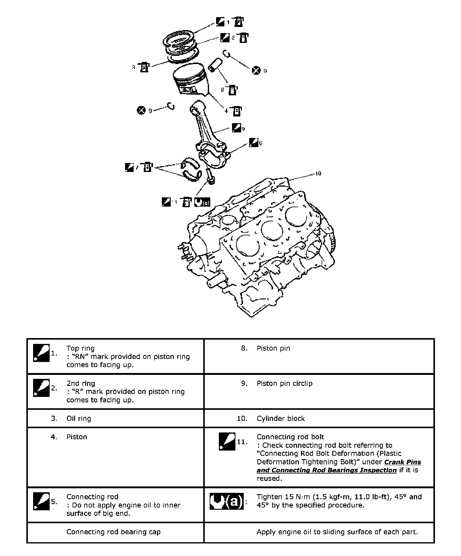
Pistons, Piston Rings, Connecting Rods and Cylinders Removal and Installation
Reference: Pistons, Piston Rings, Connecting Rods and Cylinders Components
Removal
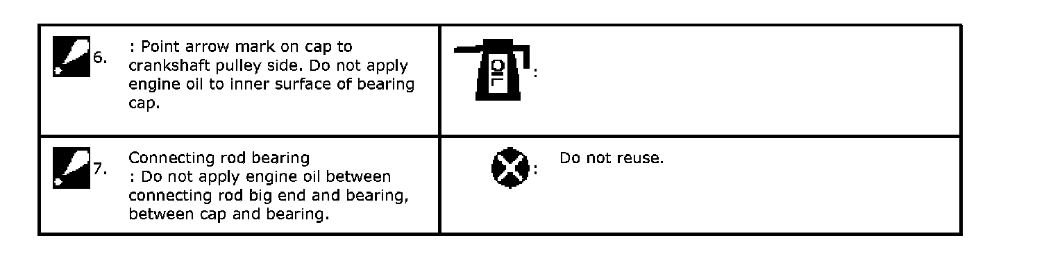
1) Remove engine assembly from vehicle.
2) Remove cylinder heads.
3) Remove oil pump.
4) Mark cylinder number on all pistons, connecting rods and connecting rod bearing caps.
5) Remove connecting rod bearing caps.
6) Clean carbon from top of cylinder bore before removing piston from cylinder.
7) Push piston and connecting rod assembly out through the top of cylinder bore.
Installation
Reference: Pistons, Piston Rings, Connecting Rods and Cylinders Disassembly and Reassembly
Reference: Cylinders, Pistons and Piston Rings Inspection
Reference: Piston Pins and Connecting Rods Inspection
Reference: Crank Pins and Connecting Rod Bearings Inspection
1) Apply engine oil to pistons, rings, cylinder walls, connecting rod bearings and crank pins.
NOTE: Do not apply oil between connecting rod and bearing or between bearing cap and bearing.
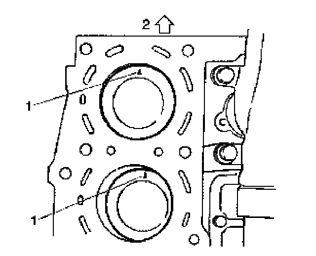
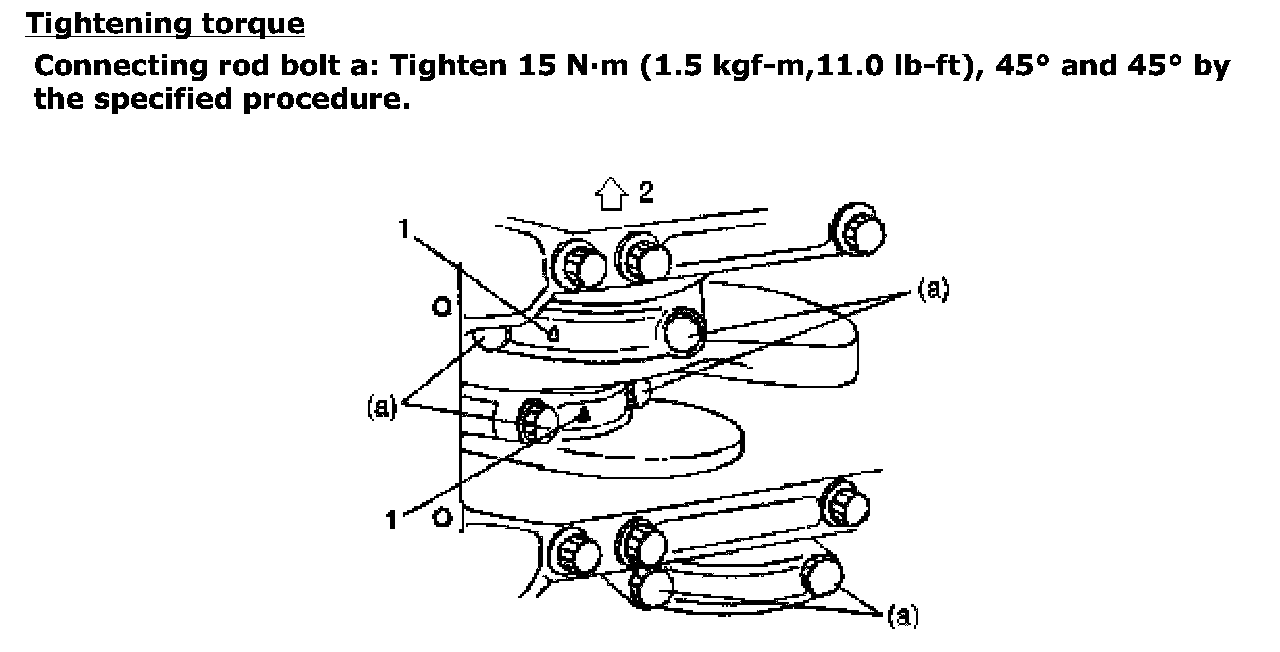
2) When installing piston and connecting rod assembly into cylinder bore, point mark (1) on piston head to crankshaft pulley side (2).
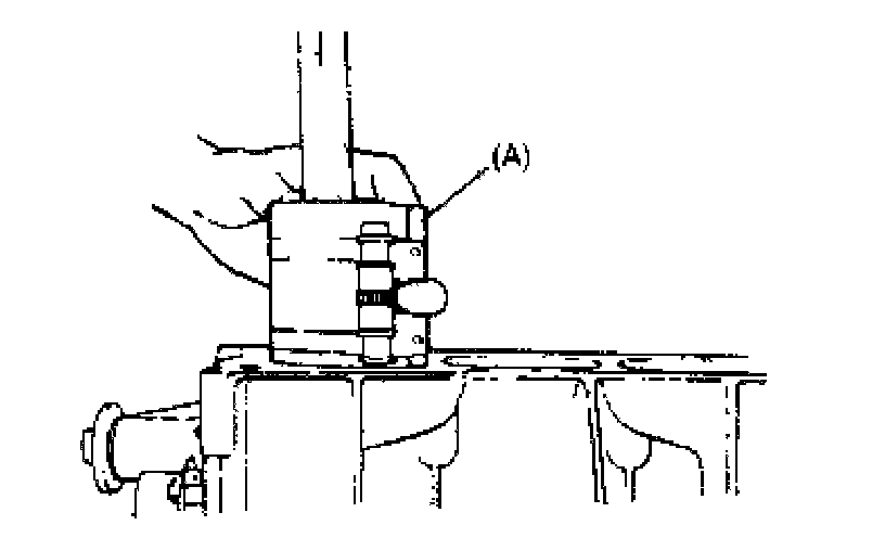
3) Install piston and connecting rod assembly into cylinder bore. Use special tool (Piston ring compressor) to compress rings. Guide connecting rod into place on crankshaft.
Using a hammer handle, tap piston head to install piston into bore. Hold ring compressor firmly against cylinder block until all piston rings have entered cylinder bore.
Special Tool
(A): 09916-77310
4) Install connecting rod bearing cap (1) as follows.
NOTE: If connecting rod bolt is reused, mark sure to check connecting rod bolt for deformation, referring to "Connecting Rod Bolt Deformation (Plastic Deformation Tightening Bolt)" under Crank Pins and Connecting Rod Bearings Inspection.
a) Point arrow mark (2) on cap to crankshaft pulley side.
b) Apply engine oil to new connecting rod bolts (3).
c) Tighten all connecting rod bolts to 15 Nm (1.5 kgf-m, 11.0 ft. lbs.).
d) Retighten them by turning through 45°
e) Repeat step d) once again.
5) Install cylinder heads to cylinder block.
6) Install oil pump to cylinder block.
7) Install tappets, shims and camshafts.
8) Install RH (No.2) bank 2nd timing chain, referring to RH (No.2) Bank 2nd Timing Chain and Chain Tensioner Removal and Installation.
9) Install 1st timing chain.
10) Install LH (No.1) bank 2nd timing chain.
11) Install timing chain cover.
12) Install oil pans and pump strainer.
13) Install cylinder head covers.
14) Install exhaust manifold.
15) Install radiator outlet pipe.
Refer to Cooling Water Pipes or Hoses Removal and Installation.
16) Install intake manifold, intake collector and electric throttle body assembly, referring to Intake Collector and Intake Manifold Removal and Installation and Electric Throttle Body Assembly Removal and Installation.
17) Install engine assembly to vehicle.