Removal and Replacement
Main Bearings, Crankshaft and Cylinder Block Components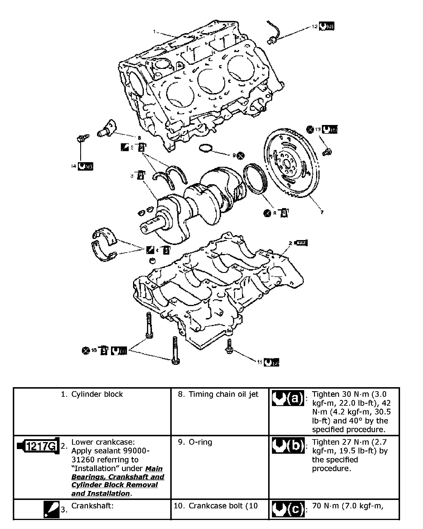
Main Bearings, Crankshaft and Cylinder Block Removal and Installation
Reference: Main Bearings, Crankshaft and Cylinder Block Components
Removal
1) Remove engine assembly from vehicle.
2) Remove clutch and flywheel (for M/T vehicle) or drive plate (for A/T vehicle).
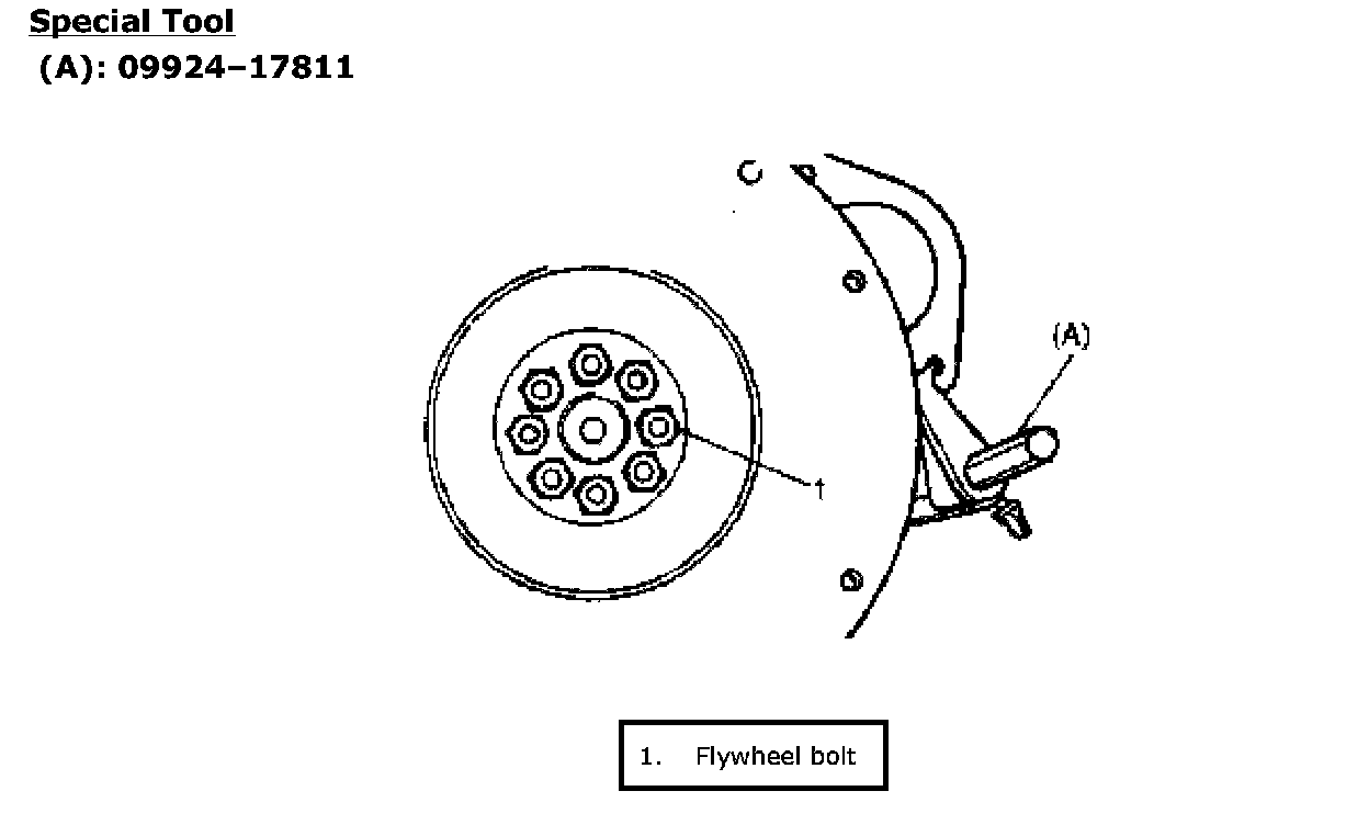
Using special tool (flywheel holder), remove flywheel (M/T vehicle) or drive plate (A/T vehicle).
Special Tool
(A): 09924-17811
3) Remove electric throttle body assembly with intake collector and intake manifold.
4) Remove oil pans (lower and upper) and oil pump strainer.
5) Remove cylinder head cover.
6) Remove timing chain cover.
7) Remove LH (No.1) bank 2nd timing chain and tensioner, referring to LH (No.1) Bank 2nd Timing Chain and Chain Tensioner Removal and Installation.
8) Remove 1st timing chain and tensioner, referring to 1st Timing Chain and Chain Tensioner Removal and Installation.
9) Remove RH (No.2) bank 2nd timing chain and tensioner, referring to RH (No.2) Bank 2nd Timing Chain and Chain Tensioner Removal and Installation.
10) Remove cylinder heads.
11) Remove pistons and connecting rods.
12) Remove oil pump.
13) Remove oil pump chain.
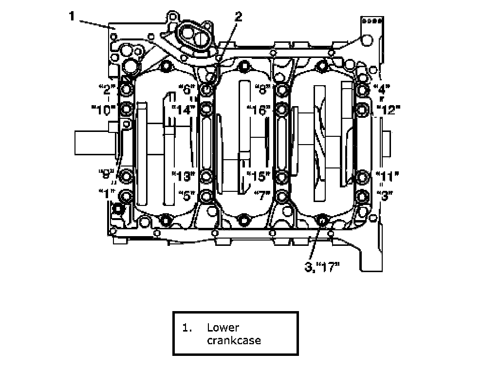
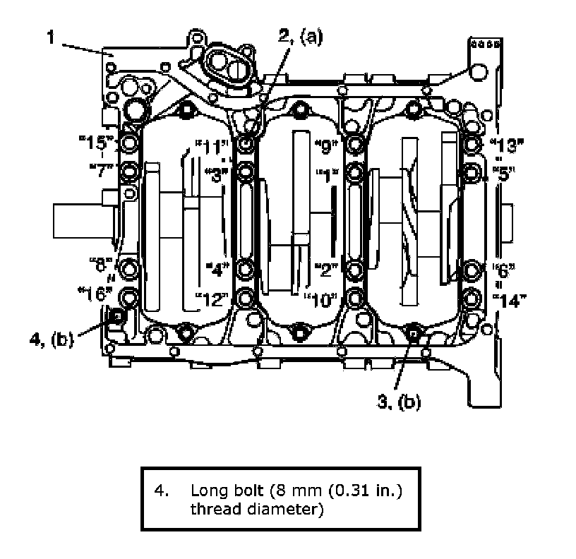
14) Loosen crankcase bolts by numerical order ("1" through "17") in figure and remove them.
NOTE: Loosen 8 mm (0.31 inch) thread diameter bolts (2) first, then loosen 10 mm (0.39 inch) thread diameter bolts (3).
15) Remove crankshaft from cylinder block.
Installation
Reference: Crankshaft Inspection
Reference: Main Bearings Inspection
Reference: Rear Oil Seal and Flywheel Inspection
Reference: Cylinder Block Inspection
NOTE:
^ All parts to be installed must be perfectly clean.
^ Be sure to apply oil crankshaft journals, main bearings, thrust bearings, crank pins, connecting rod bearings, pistons, piston rings and cylinder bores.
^ Main bearings, crankcase (bearings caps), connecting rods, connecting rod bearings, connecting rod bearing caps, pistons and piston rings are in combination sets. Do not disturb combination and try to see that each part goes back to where it came from, when installing.
^ Clean mating surface of cylinder block and crankcase, remove oil, old sealant and dust from mating surface.
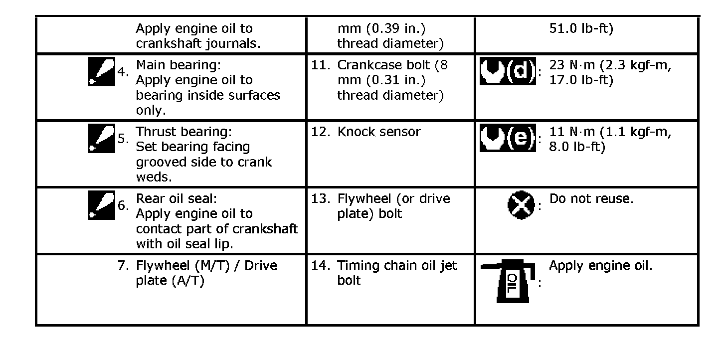
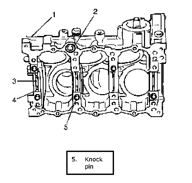
1) Fit main bearings (4) to cylinder block (1).
One of two halves of main bearing, has oil groove (3). Install this half with oil groove to cylinder block, and another half without oil groove to crankcase.
Make sure that two halves are painted in the same color.
2) Install O-ring (2) to cylinder block.
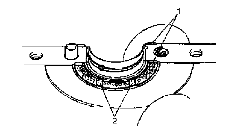
3) Fit thrust bearings (1) to cylinder block between No.4 and No.5 cylinders.
Face oil groove (2) sides to crank webs.
4) Put crankshaft to cylinder block.
5) Apply sealant "A" to lower crankcase mating surface area as shown in figure.
"A": Sealant 99000-31260SUZUKI Bond No.1217G
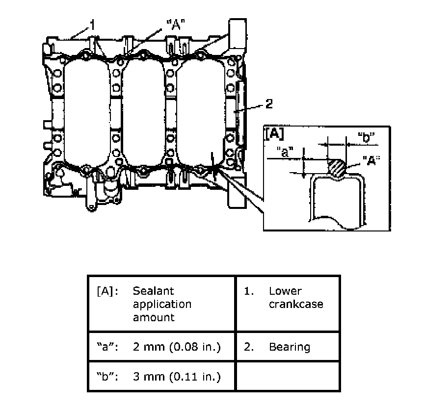
6) Install lower crankcase (1) to cylinder block. Apply oil to crankcase bolts before installing them. Tighten crankcase bolts gradually as follows.
a) Tighten crankcase bolts (10 mm (0.39 inch) thread diameter) (2) to 30 Nm (3.0 kgf-m, 22.0 ft. lbs.) according to numerical order in figure.
b) In the same manner as Step a), tighten them to 42 Nm (4.2 kgf-m, 30.5 ft. lbs.).
c) In the same manner as Step a), retighten by turning through 40°.
d) Tighten crankcase bolts (8 mm (0.31 inch) thread diameter) (3) to specified torque.
NOTE: Tighten 10 mm (0.39 inch) thread diameter bolts first (the following the order shown in figure), then tighten 8 mm (0.31 inch) thread diameter bolts.
Tightening torque
Lower crankcase bolt (10 mm (0.39 inch) thread diameter) a: Tighten 30 Nm (3.0 kgf-m,22.0 ft. lbs.), 0 Nm (0 kgf-m, 0 ft. lbs.), 42 Nm (4.2 kgf-m, 30.5 ft. lbs.) and 40° by the specified procedure
Lower crankcase bolt (8 mm (0.31 inch) thread diameter) b: 27 Nm (2.7 kgf-m, 19.5 ft. lbs.) by the specified procedure
NOTE: After tightening crankcase bolts, check to be sure that crankshaft rotates smoothly when turned by hand.
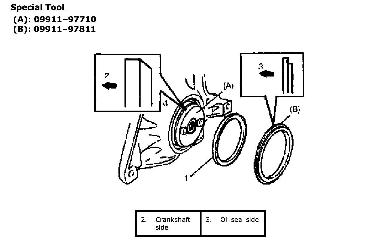
7) Using special tools (Oil seal installer and oil seal guide), install rear oil seal (1).
Special Tool
(A): 09911-97710
(B): 09911-97811
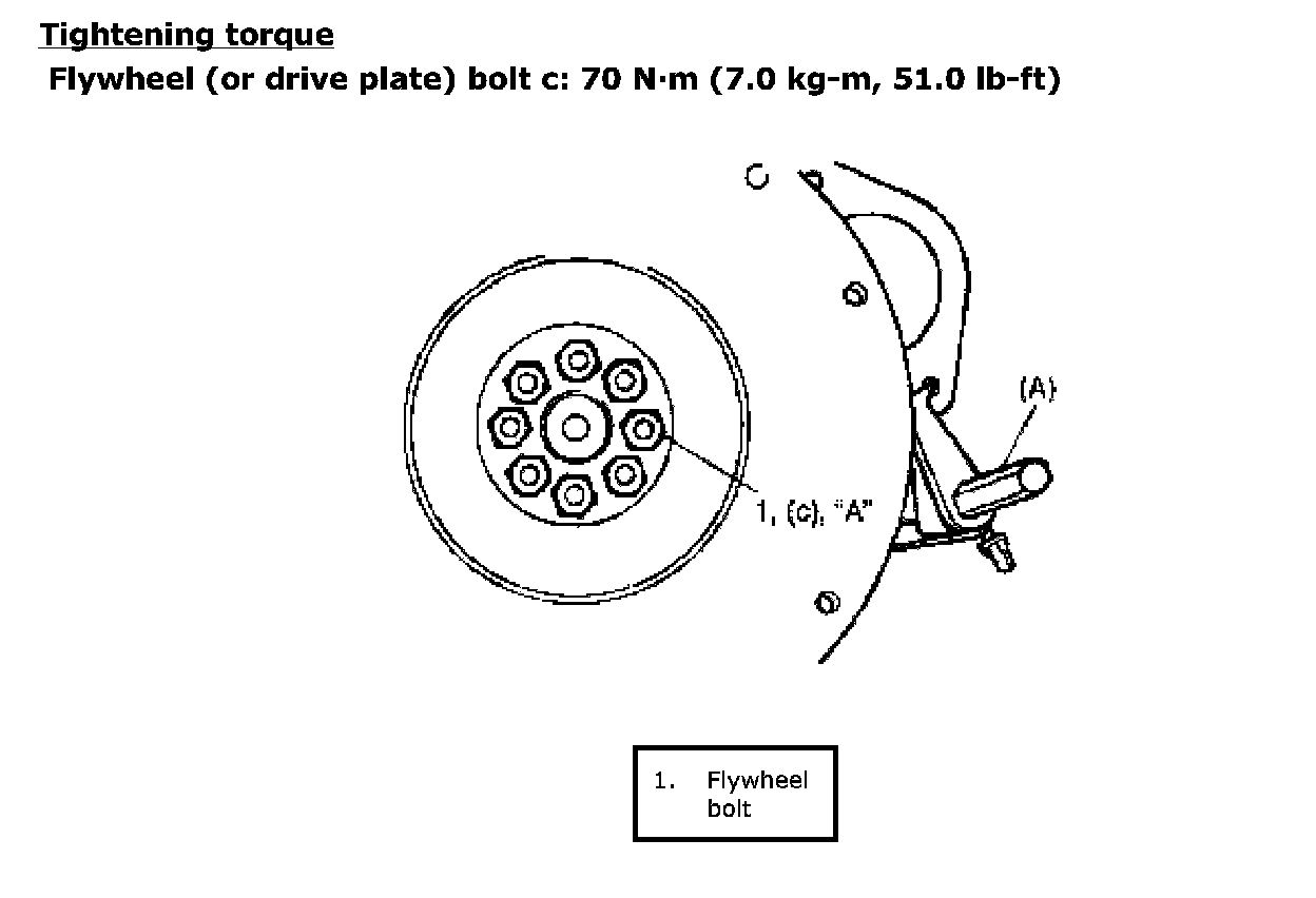
8) Install flywheel (M/T vehicle) or drive plate (A/T vehicle). Using special tool, lock flywheel or drive plate, and tighten new flywheel bolts or new drive plate bolts to specification.
Special Tool
(A): 09924-17811
Tightening Torque:
9) Install oil pump.
10) Install pistons and connecting rods.
11) Install oil pump strainer and oil pans.
12) Install cylinder heads assembly to cylinder block.
13) Install oil pump chain.
14) Install RH (No.2) bank 2nd timing chain and tensioner, referring to RH (No.2) Bank 2nd Timing Chain and Chain Tensioner Removal and Installation.
15) Install 1st timing chain and tensioner, referring to 1st Timing Chain and Chain Tensioner Removal and Installation.
16) Install LH (No.1) bank 2nd timing chain and tensioner, referring to LH (No.1) Bank 2nd Timing Chain and Chain Tensioner Removal and Installation.
17) Install timing chain cover and crankshaft pulley.
18) Install cylinder head covers.
19) Install intake manifold, intake collector and electric throttle body assembly.
20) Install clutch to flywheel (for M/T vehicle). For clutch installation, refer to Clutch Cover, Clutch Disc and Flywheel Removal and Installation.
21) Install engine assembly to vehicle.