Hydraulic Control Assembly - Antilock Brakes: Service and Repair
ABS (ESP(R)) Hydraulic Unit / Control Module Assembly Removal and InstallationCAUTION: Never disassemble ABS (ESP(R)) hydraulic unit / control module assembly, loosen blind plug or remove motor. Performing any of these prohibited services will affect original performance of ABS (ESP(R)) hydraulic unit / control module assembly.
Removal
1. Disconnect negative (-) cable from battery.
2. Remove ECM referring to Engine Control Module (ECM) Removal and Installation.
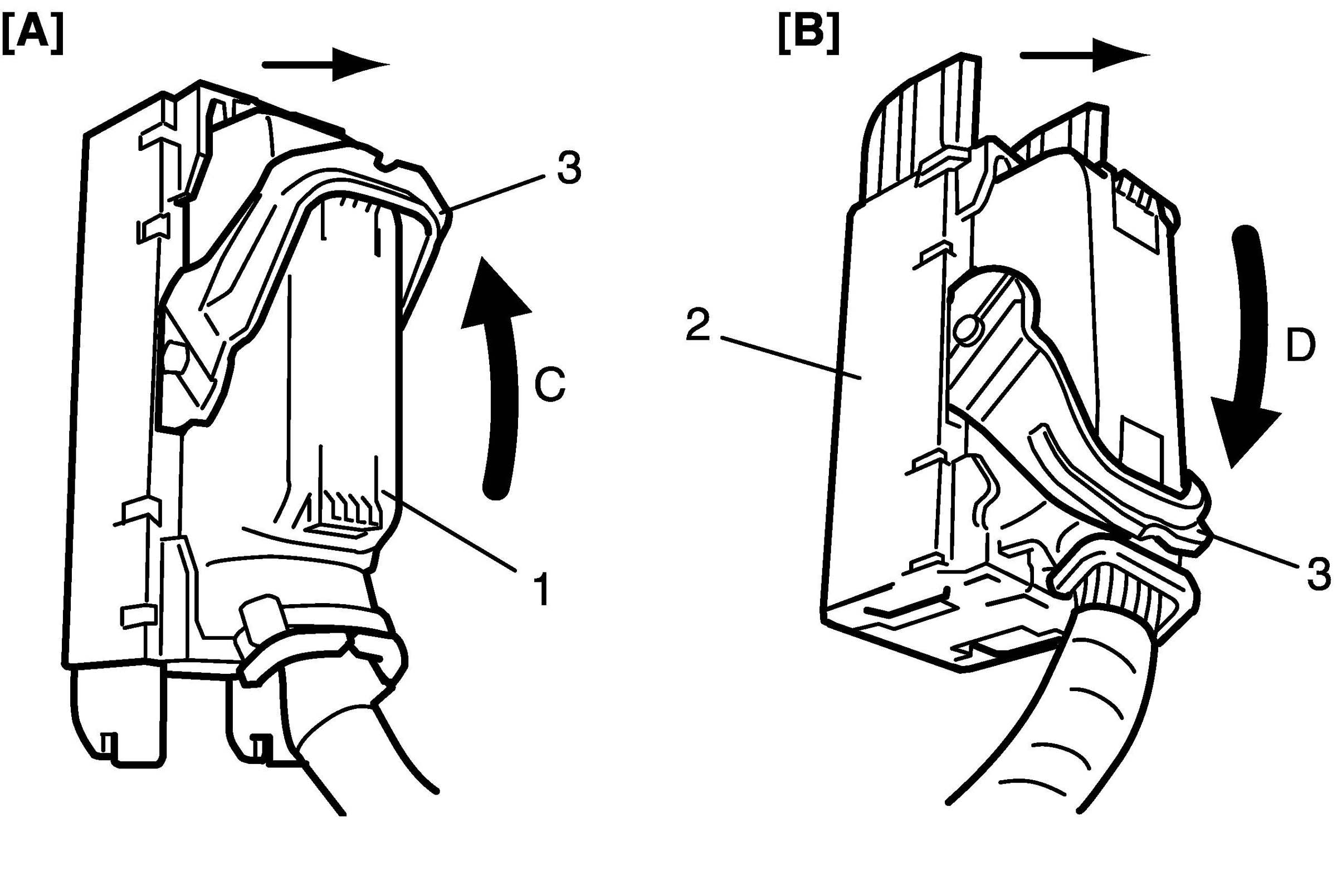
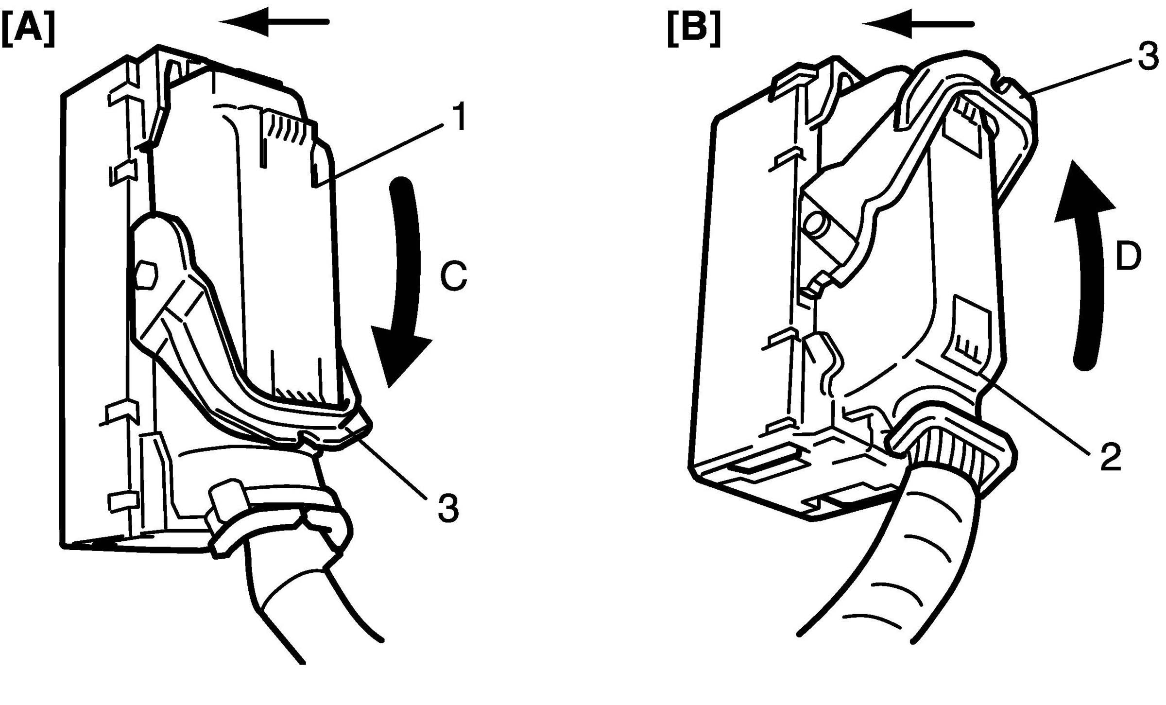
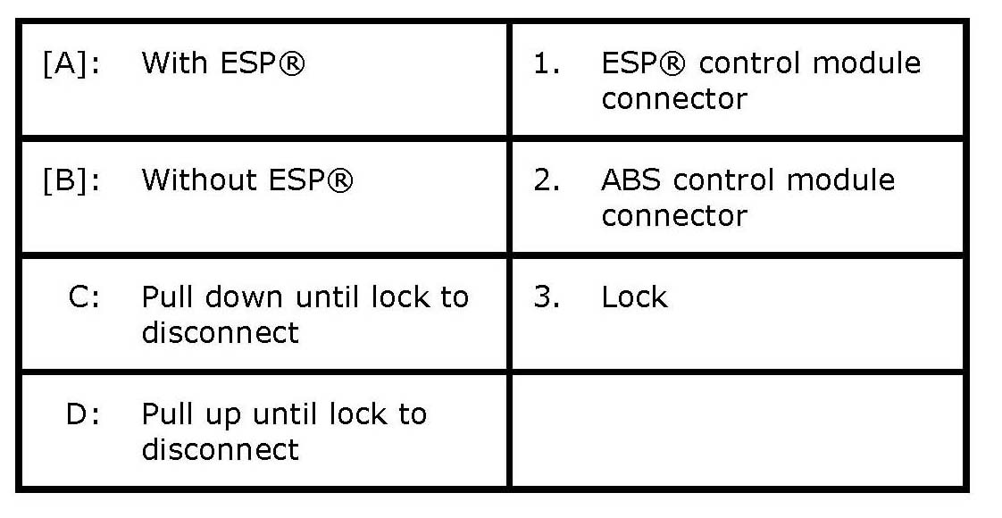
3. Disconnect ABS ESP(R) control module connector as shown in figure.
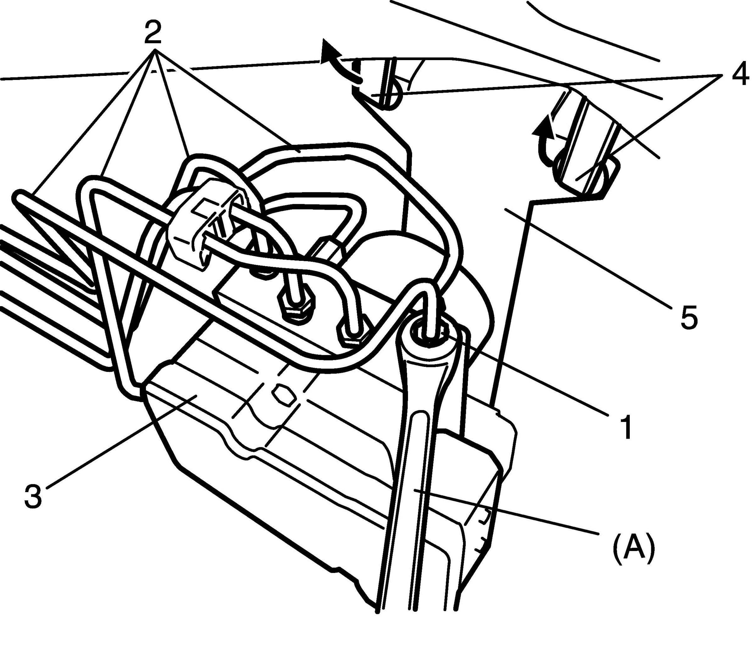
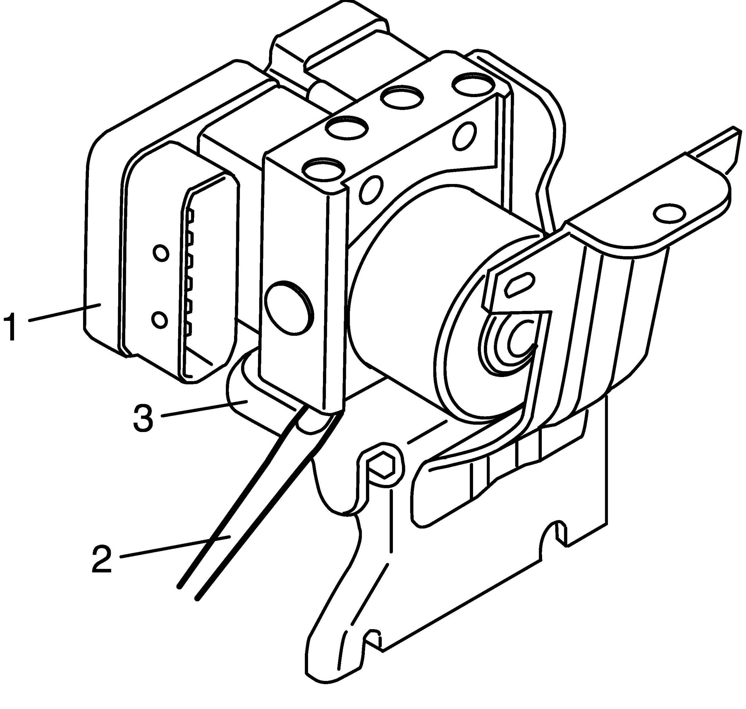
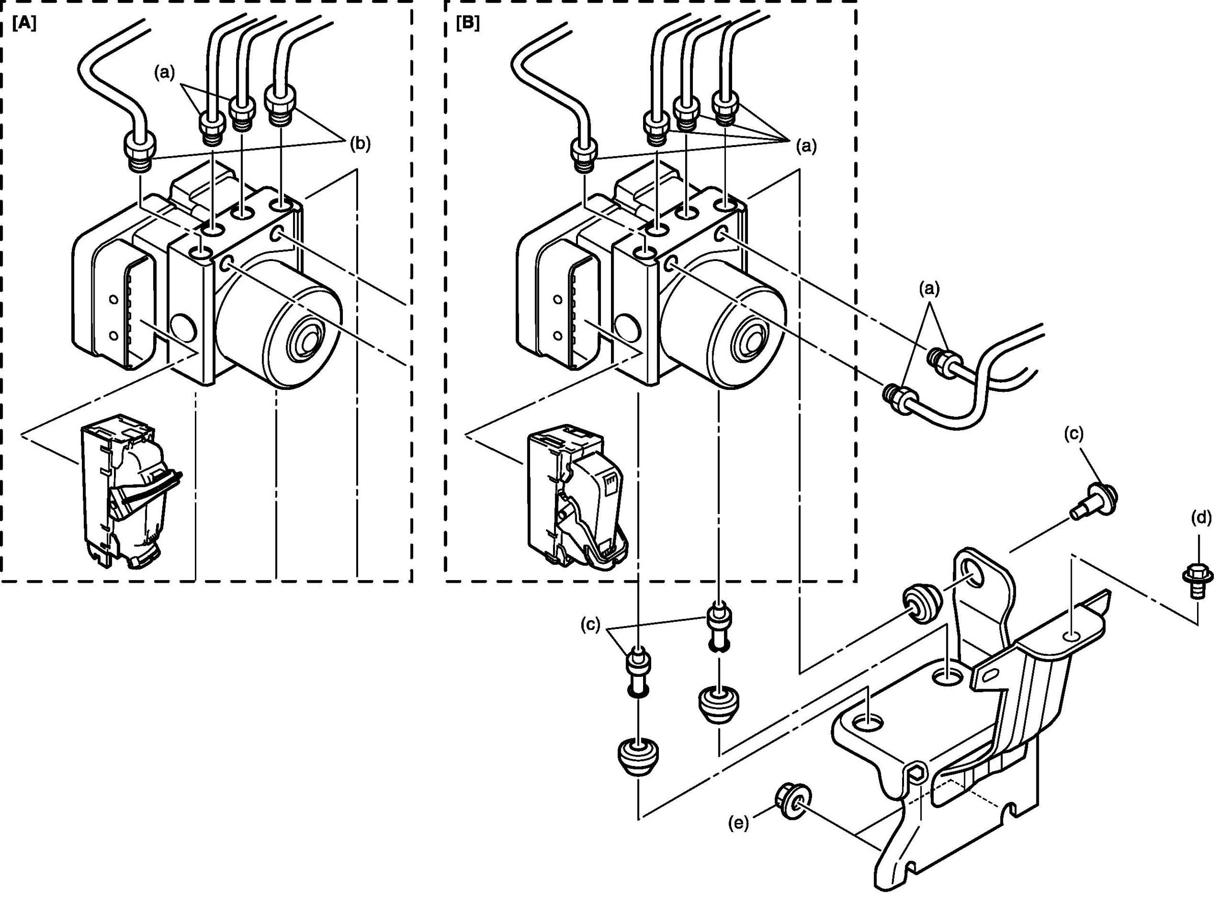
4. Using special tool, loosen flare nuts (1) and disconnect brake pipes (2) from ABS ESP(R) hydraulic unit/ control module assembly (3).
NOTE: Put bleeder plug cap or the like onto pipe to prevent fluid from spilling. Do not allow brake fluid to get on painted surfaces.
5. Disconnect harness clamps (4) from bracket (5).
6. Remove ABS ESP(R) hydraulic unit / control module with bracket from vehicle by removing bracket bolt and two bracket nuts.
7. Remove bolt and pull out ABS ESP(R) hydraulic unit / control module assembly (1) from bracket (3) using flat end rod or the like (2).
CAUTION:
^ Do not give an impact to hydraulic unit.
^ Use care not to allow dust to enter hydraulic unit.
^ Do not place hydraulic unit on its side or upside down. Handling it in inappropriate way will affect its original performance.
Installation
1. Install hydraulic unit / control module assembly by reversing removal procedure.
Tightening torque
Brake pipe flare nut for M10 a: 16 N-m (1.6 kg-m, 11.5 lb-ft)
Brake pipe flare nut for M12 b: 19 N-m (1.9 kg-m, 14.0 lb-ft)
ABS (ESP(R)) hydraulic unit / control module assembly bolt c: 9 N-m (0.9 kg-m, 6.5 lb-ft)
ABS (ESP(R)) hydraulic unit / control module assembly bracket bolt d: 25 N-m (2-5 kg-m, 18.0 lb-ft)
ABS (ESP(R)) hydraulic unit / control module assembly bracket nut e: 25 N-m (2-5 kg-m, 18.0 lb-ft)
2. Connect ABS ESP(R) control module connector and lock it as shown in figure.
3. Connect harness clamp to bracket.
4. Install ECM referring to Engine Control Module (ECM) Removal and Installation.
5. Connect negative (-) cable at battery.
6. Bleed air from brake system referring to Air Bleeding of Brake System.
7. Check each installed part for fluid leakage and perform Hydraulic Unit Operation Check.
NOTE:
For new ABS (ESP(R)) hydraulic unit / control module assembly, if Hydraulic Unit Operation Check has not been performed, ABS warning light may flash when ignition switch is turned ON position.
Accordingly perform Hydraulic Unit Operation Check to stop flashing of ABS warning light.