Brake Light Switch with Pedal Position Switch Circuits Check
TEST PROCEDURE - BRAKE LIGHT SWITCH WITH PEDAL POSITION SWITCH CIRCUITS
| Step |
Action |
YES |
NO |
| 1 |
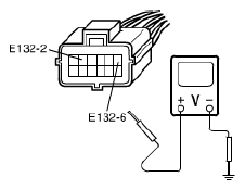
Brake light switch with pedal position switch circuits check
- Disconnect connector from cruise control module with ignition switch OFF.
- Check for proper connection to cruise control module at terminals "E132-2" and "E132-6".
- If OK, turn ignition switch ON.
- Check Voltage between each terminal and ground under each condition in the following.
Brake light switch circuit specifications
Brake pedal released terminal "E132-2": 0 V
Brake pedal released terminal "E132-6": 10 - 14 V
Brake pedal depressed terminal "E132-2": 10 - 14 V
Brake pedal depressed terminal "E132-6": 0 V
 Courtesy of SUZUKI OF AMERICA CORP. Courtesy of SUZUKI OF AMERICA CORP.
Is check result satisfactory? |
Brake light switch with pedal position switch circuits are OK. |
Go to Step 2. |
| 2 |
Brake light switch position check
- Check brake light switch for installation position referring to BRAKE LIGHT SWITCH ADJUSTMENT
.
Is check result satisfactory? |
Go to Step 3. |
Adjust brake light switch position. |
| 3 |
Brake light switch with pedal position switch check
- Disconnect connector from brake light switch.
- Check for proper connection to brake light switch at all terminals.
- If OK, check brake light and pedal position switches for operation referring to BRAKE LIGHT SWITCH INSPECTION
.
Is this switch in good condition? |
"YEL/GRN" or "GRN/WHT" circuit is open or short. |
Replace brake light switch. |