| 1 |
Was "A/T System Check" performed? |
Go to Step 2. |
Go to A/T SYSTEM CHECK . |
| 2 |
DTC check
- Check DTC of ECM, TCM and BCM.
Is there any DTC(s) (other than DTC U0001 in ECM, DTC U0001 in TCM and DTC in BCM)? |
Go to applicable DTC diag. flow. |
Go to Step 3. |
| 3 |
Circuit check
- Turn OFF ignition switch.
- Disconnect connectors from TCM and BCM.
- Check for proper connection to TCM and BCM at applicable terminals.
- If OK, measure resistance between "E229-1" terminal of TCM connector and "G53-9" terminal of BCM connector, between "E229-2" terminal of ECM connector and "G53-1" terminal of BCM connector.
Is each resistance 1 Ω or less? |
Go to Step 4. |
"WHT" wire circuit (between "E229-1" terminal of TCM connector and "G53-9" terminal of BCM connector) or "RED" wire circuit (between "E229-2" terminal of ECM connector and "G53-1" terminal of BCM connector) open or high resistance. |
| 4 |
Circuit check
- Disconnect connectors from ECM.
- Check for proper connection to ECM at applicable terminals.
- If OK, measure resistance between "E229-1" terminal of TCM connector and "E61-32" terminal of ECM connector, between "E229-2" terminal of TCM connector and "E61-33" terminal of ECM connector.
Is each resistance 1 Ω or less? |
Go to Step 5. |
"WHT" wire or "RED" wire in shorted to power circuit. |
| 5 |
Circuit check
- Measure resistance between "E61-32" terminal of ECM connector and "G53-9" terminal of BCM connector, between "E61-33" terminal of ECM connector and "G53-1" terminal of BCM connector.
Is each resistance 1 Ω or less? |
Go to Step 6. |
"WHT" wire circuit (between "E61-32" terminal of ECM connector and "G53-9" terminal of BCM connector) or "RED" wire circuit (between "E61-33" terminal of ECM connector and "G53-1" terminal of BCM connector) open or high resistance. |
| 6 |
Circuit check
- Turn ignition switch to ON position.
- Measure voltage between "E229-1" terminal of TCM connector and vehicle body ground, between "E229-2" terminal of TCM connector and vehicle body ground.
Is each voltage 0 - 1 V? |
Go to Step 7. |
"WHT" circuit or "RED" circuit shorted to power supply line. |
| 7 |
Circuit check
- Turn ignition switch to OFF position.
- Measure resistance between "E229-1" terminal of TCM connector and vehicle body ground, between "E229-1" terminal of TCM connector and vehicle body ground.
As they infinite? |
Go to Step 8. |
"WHT" circuit or "RED" circuit shorted to ground. |
| 8 |
Circuit check
- Measure resistance between "E229-1" and "E229-2" terminals of TCM connector.
Is it infinite? |
Go to Step 9. |
"WHT" circuit is shorted to "RED" circuit. |
| 9 |
Do you have oscilloscope? |
Go to Step 10. |
Substitute a known-good BCM and recheck. If malfunction is detected, substitute a known-good TCM and recheck. If malfunction is detected, substitute a known-good ECM and recheck. |
| 10 |
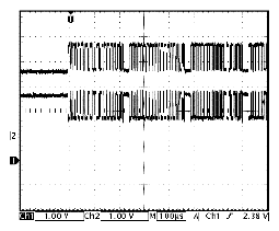
Waveform range check
- Connect connectors to ECM, TCM and BCM.
- Connect oscilloscope between "E229-1" terminal of TCM connector and ground, between "E229-2" terminal of TCM connector and ground.
- Check if each range of two waveforms is as specified in illustration below.
 Courtesy of SUZUKI OF AMERICA CORP. Courtesy of SUZUKI OF AMERICA CORP.
Is it in good condition? |
Go to Step 13. |
Go to Step 11. |
| 11 |
Waveform range check
- Disconnect connectors from BCM.
- Connect oscilloscope between "E229-1" terminal of TCM connector and ground, between "E229-2" terminal of TCM connector and ground.
- Check if each range of two waveforms is as specified in illustration below.
 Courtesy of SUZUKI OF AMERICA CORP. Courtesy of SUZUKI OF AMERICA CORP.
Is it in good condition? |
Substitute a known-good BCM and recheck. |
Go to Step 12. |
| 12 |
Waveform range check
- Disconnect connectors from TCM.
- Connect connectors to BCM.
- Connect oscilloscope between "E61-32" terminal of ECM connector and ground, between "E61-33" terminal of ECM connector and ground.
- Check if each range of two waveforms is as specified in illustration below.
 Courtesy of SUZUKI OF AMERICA CORP. Courtesy of SUZUKI OF AMERICA CORP.
Is it in good condition? |
Substitute a known-good TCM and recheck. |
Substitute a known-good ECM and recheck. |
| 13 |
Communication check
- Disconnect connector from input shaft speed sensor.
- Start engine for 1 minute or more.
- Check DTC of ECM referring to DTC CHECK
.
Is DTC U0001 indicated? |
Go to Step 14. |
Substitute a known-good ECM and recheck. |
| 14 |
Communication check
- Connect connector to input shaft speed sensor.
- Disconnect connector from ECT sensor.
- Perform "DTC Confirmation Procedure" referring to DTC P0118: ENGINE COOLANT TEMPERATURE CIRCUIT HIGH
.
- Check DTC for TCM referring to DTC Check .
Is DTC U0001 indicated? |
Substitute a known-good BCM and recheck. |
Substitute a known-good TCM and recheck. |