DTC Check
DTC CheckUsing ABS Warning Lamp
1) Perform ABS Warning Lamp Check. ABS Warning Lamp Check
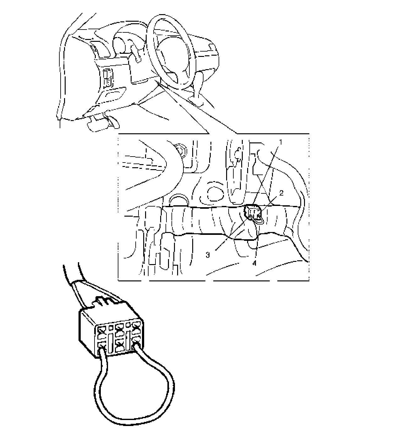
2) Using service wire (4), connect diagnosis switch PNK wire terminal (2) of monitor coupler (1) to BLK wire terminal (3).
3) Turn ignition switch ON.
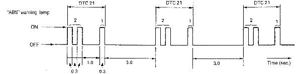
4) Read flashing of ABS warning lamp which represents DTC as shown in example below and write it down. When more than 2 DTCs are stored in memory, flashing for each DTC is repeated three times starting with the smallest DTC number in increasing order.
For details of DTC, refer to DTC Table.
If no DTC output is available, check according to DTC Is Not Outputted even with Diag. Switch Terminal Connected to Ground. DTC Is Not Outputted Even With Diag. Switch Terminal
Example: When right-front wheel speed sensor circuit opens (DTC 21)
Example: When Right-Front Wheel Speed Sensor Circuit Opens (DTC 21):
5) After completing the check, turn ignition switch OFF, disconnect service wire from monitor coupler.
Using SUZUKI Scan Tool
1) Turn ignition switch to OFF position.
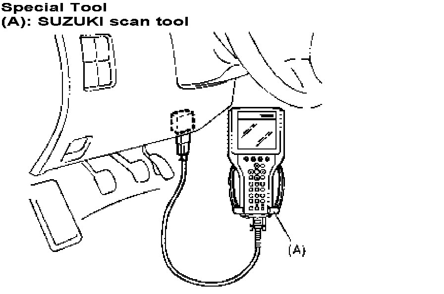
2) Connect SUZUKI scan tool to data link connector.
Special Tool
(A): SUZUKI scan tool
3) Turn ignition switch ON.
4) Read DTC according to instructions displayed on SUZUKI scan tool and print it or write it down. Refer to SUZUKI scan tool operator's manual for further details.
5) After completing the check, turn ignition switch OFF and disconnect SUZUKI scan tool from DLC.
If communication between SUZUKI scan tool and ABS hydraulic unit/control module is not possible, check if SUZUKI scan tool is communicable by connecting it to ABS case, SUZUKI scan tool is in good condition. Then check data link connector and serial data line (circuit) in the vehicle with which communication was not possible.