Instrument Panel Removal
- Disconnect the negative battery cable.
- Remove the floor console. Refer to FLOOR CONSOLE REMOVAL
.
- Remove the sun sensor. Refer to SUN SENSOR REMOVAL
.
- Remove the tweeter speakers and the stereo cassette AM/FM radio. Refer to TWEETER SPEAKERS REMOVAL
and STEREO CASSETTE AM/FM RADIO REMOVAL
.
- Remove the instrument cluster dimmer switch assembly. Refer to Instrument Cluster Dimmer / Headlamp Leveling Switch Removal .
- Remove the instrument cluster trim panel. Refer to Instrument Cluster Trim Panel Removal .
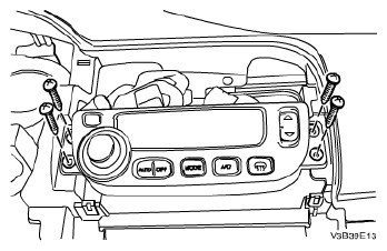
- Remove the automatic temperature controls assembly. Refer to AUTOMATIC TEMPERATURE CONTROL ASSEMBLY REMOVAL
.
- Remove the instrument cluster. Refer to Instrument Cluster Removal .
- Remove the kick panels. Refer to KICK PANEL REMOVAL
.
- Remove the glove box. Refer to Glove Box Removal .
- Remove the screws and the glove box housing.
- Disconnect the glove box housing electrical connectors.
- Remove the knee bolster. Refer to DRIVER'S SIDE KNEE BOLSTER REMOVAL
.
 Courtesy of SUZUKI OF AMERICA CORP.
- Remove the screws and the instrument panel side covers.
- Remove the screw and instrument panel fuse block.
 Courtesy of SUZUKI OF AMERICA CORP.
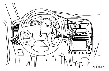
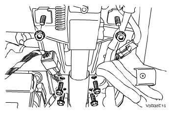
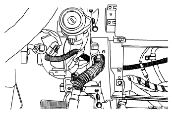
- Remove the nuts and the bolts securing the steering column.
- Disconnect the steering column electrical connector.
- Lower the steering column.
 Courtesy of SUZUKI OF AMERICA CORP.
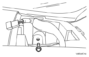
- Remove the instrument panel bolts below the windshield.
 Courtesy of SUZUKI OF AMERICA CORP.
- Remove the fixing screws securing the instrument panel.
 Courtesy of SUZUKI OF AMERICA CORP.
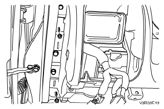
- Remove the nuts securing the sides of the instrument panel to the body.
- Disconnect the instrument panel electrical connectors.
- Remove the instrument panel.
 Courtesy of SUZUKI OF AMERICA CORP.