Transaxle Assembly Removal and Installation: Removal
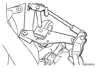
- Install the engine assembly support fixture DW110-060.
- Remove the battery and battery tray. Refer to BATTERY AND BATTERY TRAY REMOVAL AND INSTALLATION
.
- Remove the shift linkage assembly. Refer to Shift Linkage Assembly Removal and Installation .
- Remove the drive axle shaft. Refer to DRIVE AXLE ASSEMBLY REMOVAL AND INSTALLATION
.
 Courtesy of SUZUKI OF AMERICA CORP.
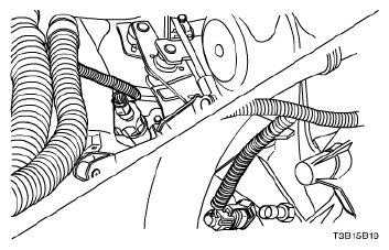
- Disconnect the backup lamp switch electrical connector.
- Disconnect the speedometer speed sensor electrical connector.
 Courtesy of SUZUKI OF AMERICA CORP.
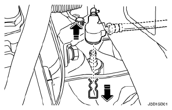
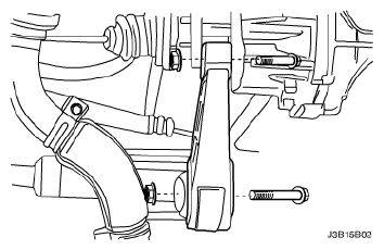
- Remove the pin and the clutch release cylinder pipe.
 Courtesy of SUZUKI OF AMERICA CORP.
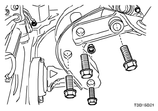
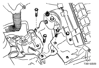
- Remove the damping block connection nut and bolt.
- Remove the three rear mounting bracket bolts.
- Remove the rear mounting bracket from the transaxle.
 Courtesy of SUZUKI OF AMERICA CORP.
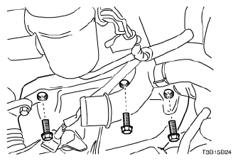
- Remove the two rear damping block retaining bolts.
- Remove the rear damping block from the front cross member.
 Courtesy of SUZUKI OF AMERICA CORP.
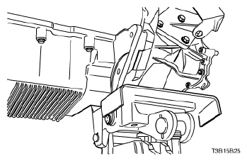
- Remove the two cage retaining bolts.
- Remove the three transaxle upper mounting bracket bolts.
- Remove the upper mounting bracket and cage.
 Courtesy of SUZUKI OF AMERICA CORP.
- Remove the three transaxle upper retaining bolts.
 Courtesy of SUZUKI OF AMERICA CORP.
- Support the transaxle with a transaxle support jack.
 Courtesy of SUZUKI OF AMERICA CORP.
- Remove the seven transaxle lower retaining bolts.
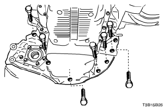 Courtesy of SUZUKI OF AMERICA CORP.
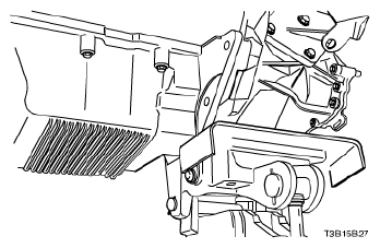
- Remove the transaxle.
- Slide the transaxle sideways away from the engine block.
- Lower the transaxle.
 Courtesy of SUZUKI OF AMERICA CORP.