Knuckle Assembly Removal and Installation: Removal
- Raise and suitably support the vehicle.
- Remove the wheel. Refer to WHEEL REMOVAL AND INSTALLATION
.
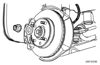
- Remove the caulking nut from the axle shaft.
 Courtesy of SUZUKI OF AMERICA CORP.
- Remove the brake caliper from the rotor. Support the caliper so it does not hang from the hydraulic brake hose. Refer to CALIPER ASSEMBLY REMOVAL AND INSTALLATION
.
- Remove the outer tie rod from the knuckle assembly. Refer to OUTER TIE ROD REMOVAL AND INSTALLATION
.
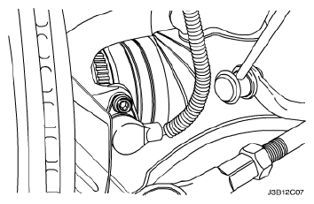
- On vehicles equipped with the Antilock Braking System (ABS), disconnect the ABS speed sensor electrical connection from the knuckle.
 Courtesy of SUZUKI OF AMERICA CORP.
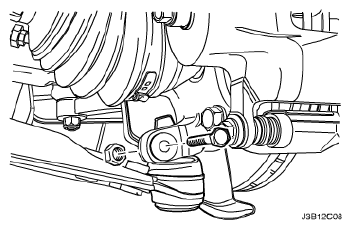
- Remove the ball joint pinch bolt and the nut.
 Courtesy of SUZUKI OF AMERICA CORP.
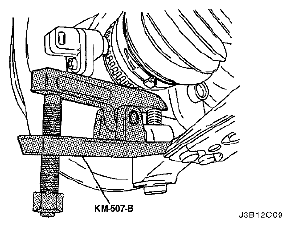
- Separate the knuckle from the ball joint using the ball joint remover KM-507-B.
 Courtesy of SUZUKI OF AMERICA CORP.
- Remove the nuts from the bolts that connect the knuckle assembly to the strut assembly.
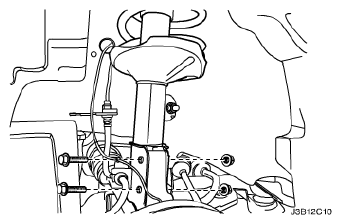 Courtesy of SUZUKI OF AMERICA CORP.
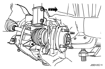
- Support the drive axle.
- Separate the drive axle shaft from the wheel hub.
- Remove the bolts that connect the knuckle assembly to the strut assembly.
- Remove the knuckle assembly from the vehicle.
 Courtesy of SUZUKI OF AMERICA CORP.