Crossmember Assembly Removal and Installation: Removal
- Raise and suitably support the vehicle.
- Remove the wheels. Refer to WHEEL REMOVAL AND INSTALLATION
.
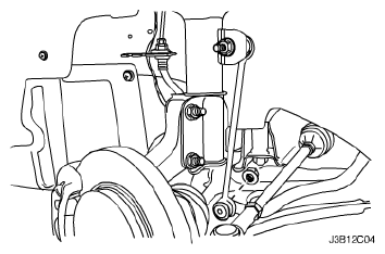
- Remove the nuts and bolts from the steering gear mounting bracket.
- Remove the return line bolt from the clip on the crossmember.
- Remove the exhaust pipe forward of the catalytic converter. Refer to EXHAUST FRONT PIPE REMOVAL AND INSTALLATION
.
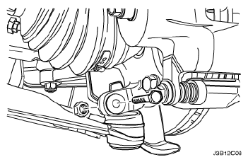
- Disconnect the tie rod from the knuckle assembly. Refer to OUTER TIE ROD REMOVAL AND INSTALLATION
.
- Disconnect the ball joint from the knuckle assembly. Refer to Knuckle Assembly Removal and Installation .
- Disconnect the stabilizer link from the strut assembly. Refer to Stabilizer Link Removal and Installation .
- Remove the crossmember link-to-transaxle bracket nut.
- Remove the right lower engine mount.
- Remove the rear transmission mount bracket.
 Courtesy of SUZUKI OF AMERICA CORP.
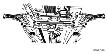
- Remove the rear crossmember-to-body bolts.
 Courtesy of SUZUKI OF AMERICA CORP.
- Remove the front crossmember-to-body bolts.
- Remove the crossmember assembly from the vehicle.
 Courtesy of SUZUKI OF AMERICA CORP.