Engine Removal and Installation: Removal
- Remove the fuel pump fuse.
- Start the engine. After it stalls, crank the engine for 10 seconds to rid the fuel system of fuel pressure.
- Remove the hood. Refer to HOOD REMOVAL AND INSTALLATION
.
- Drain the engine oil.
- Disconnect the negative battery cable.
 Courtesy of SUZUKI OF AMERICA CORP.
- Discharge the air conditioning (A/C) system, if equipped. Refer to DISCHARGING, ADDING OIL, EVACUATING, AND CHARGING PROCEDURES FOR A/C SYSTEM
.
- Disconnect the Manifold Air Temperature (MAT) sensor connector.
- Remove the air cleaner outlet hose from the throttle body and air cleaner housing.
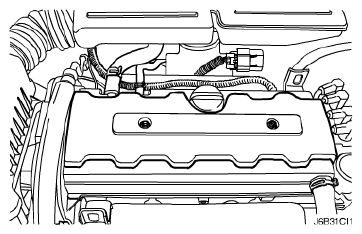
- Disconnect the breather tubes from the camshaft cover.
- Remove the right front wheel. Refer to WHEEL REMOVAL AND INSTALLATION
.
- Remove the right front wheel well splash shield.
- Remove the serpentine accessory drive belt. Refer to SERPENTINE ACCESSORY DRIVE BELT REMOVAL AND INSTALLATION
.
 Courtesy of SUZUKI OF AMERICA CORP.
- Drain the engine coolant. Refer to DRAINING AND REFILLING THE COOLING SYSTEM
.
- Remove the cooling system radiator and the engine cooling fans. Refer to RADIATOR REMOVAL AND INSTALLATION
.
- Disconnect the upper radiator hose from the thermostat housing.
- Disconnect the power steering return hose from the power steering pump.
- Disconnect the power steering pressure hose from the power steering pump.
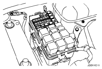
- Disconnect the electrical connector at the Direct Ignition System (DIS) coil and the Engine Control Module (ECM) ground terminal and at the starter motor.
 Courtesy of SUZUKI OF AMERICA CORP.
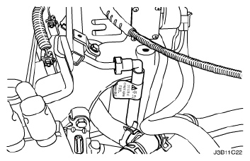
- Disconnect the Oxygen (O2) sensor connector, if equipped.
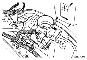
- Disconnect the Electric Throttle Control (ETC) connector.
- Disconnect the engine Coolant Temperature Sensor (CTS) connector.
- Disconnect the generator voltage regulator connector and power lead.
 Courtesy of SUZUKI OF AMERICA CORP.
- Disconnect all of the necessary vacuum lines, including the brake booster vacuum hose.
- Disconnect the fuel return line at the fuel rail.
- Disconnect the fuel feed line at the fuel rail.
- Remove the fuel rail and injector channel cover as an assembly. Refer to FUEL RAIL AND INJECTORS REMOVAL AND INSTALLATION
.
- Disconnect the coolant hose at the throttle body.
- Disconnect the heater outlet hose at the coolant pipe.
- Disconnect the coolant bypass hose from the cylinder head.
- Disconnect the surge tank coolant hose from the coolant pipe.
- Disconnect the lower radiator hose from the coolant pipe.
- Disconnect the starter solenoid "S" terminal wire and power lead.
- Remove the A/C compressor. Refer to COMPRESSOR REMOVAL AND INSTALLATION
.
 Courtesy of SUZUKI OF AMERICA CORP.
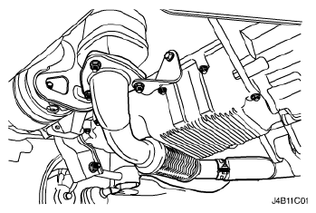
- Remove the exhaust flex pipe retaining nuts from the exhaust manifold studs.
- Remove the exhaust flex pipe retaining nuts from the catalytic converter or the connecting pipe.
- Remove the exhaust flex pipe.
 Courtesy of SUZUKI OF AMERICA CORP.
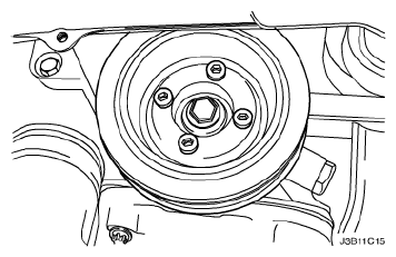
- Remove the crankshaft pulley bolts.
- Remove the crankshaft pulley.
- Disconnect the vacuum lines at the charcoal canister purge solenoid.
- Disconnect the electrical connector at the Charcoal Canister Purge (CCP) and the Exhaust Gas Recirculation (EGR) solenoid.
- Disconnect the electrical connector at the oil pressure switch.
- Disconnect the Crankshaft Position Sensor (CPS) connector.
- Disconnect the knock sensor connector.
 Courtesy of SUZUKI OF AMERICA CORP.
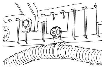
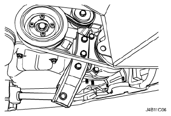
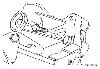
- Remove the lower reaction rod bracket bolts.
- Remove the lower reaction rod bracket.
- Remove the lower reaction rod mount bolt.
- Remove the lower reaction rod mount.
 Courtesy of SUZUKI OF AMERICA CORP.
- Remove the rubber cover as a service hole.
- Remove the transaxle torque converter bolts through the service hole, if automatic transaxle equipped.
- Remove the transaxle bell housing bolts and the oil pan flange bolts.
- Support the transaxle with a floor jack.
- Install the engine lifting device.
 Courtesy of SUZUKI OF AMERICA CORP.
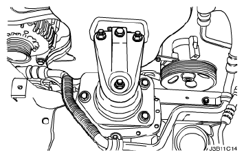
- Disconnect the right engine mount bracket from the engine mount by removing the retaining bolt.
- Remove the right engine mount bracket from the engine block and frame mount. Refer to Engine Mount Removal and Installation .
- Separate the engine block from the transaxle. Remove the engine.
 Courtesy of SUZUKI OF AMERICA CORP.