Engine Assembly Removal And Installation: Removal
- Release fuel pressure in fuel feed line referring to FUEL PRESSURE RELIEF PROCEDURE
.
- Remove battery and battery tray.
- Remove surge tank cover.
- Remove air cleaner assembly and air cleaner outlet hose referring to AIR INTAKE SYSTEM COMPONENTS .
- Drain engine oil referring to ENGINE OIL AND FILTER CHANGE
.
- Drain coolant referring to COOLING SYSTEM DRAINING
.
- Drain transmission oil or A/T fluid referring to MANUAL TRANSMISSION OIL CHANGE
or A/T FLUID CHANGE
.
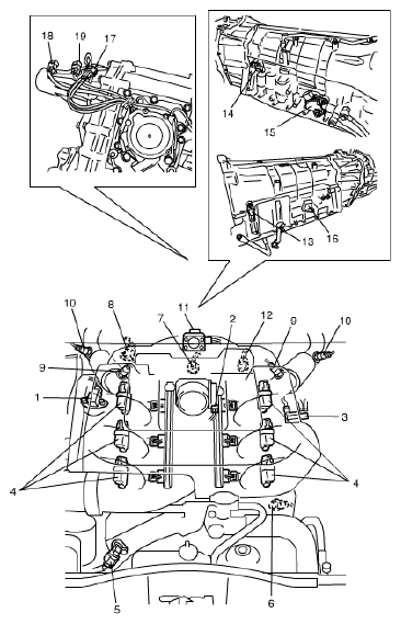
- Disconnect the following electric wires.
- MAP sensor (1)
- Injector harness
- Electric throttle body (2)
- EVAP canister purge valve (3)
- Ignition coil assemblies (4)
- CMP sensor (5)
- Generator
- Starting motor
- Pressure switch of P/S pump (6)
- Magnet clutch switch of A/C compressor (if equipped)
- Engine oil pressure switch
- Ground terminals
- Knock sensor (7)
- CKP sensor (8)
- A/F sensor (No. 1 and No. 2) (9)
- HO2S (No. 1 and No. 2) (10)
- EGR valve (11)
- ECT sensor (12)
- Back up light switch (for M/T model)
- Input shaft speed sensor (for A/T model) (13)
- Output shaft speed sensor (for A/T model) (14)
- Transmission range sensor (for A/T model) (15)
- Transmission wire connector (for A/T model) (16)
- Transfer actuator (if equipped) (17)
- Center differential switch (if equipped) (18)
- 4 L/N switch (if equipped) (19)
- Each wire harness clamps
 Courtesy of SUZUKI OF AMERICA CORP.
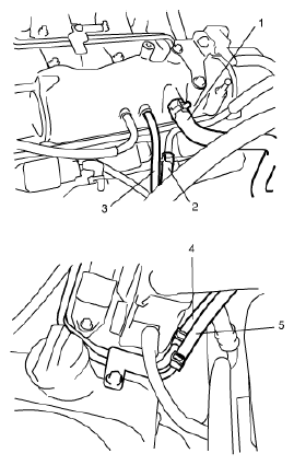
- Disconnect the following hoses.
- Brake booster hose (1) from intake manifold
- EVAP canister purge hose (2) from fuel No. 2 pipe.
- Vacuum tank hose (3) from intake manifold
- IMT hose from IMT valve
- Radiator inlet hose and outlet hose from each pipe.
- Heater inlet hose and outlet hose from each pipe
- Fuel feed hose (4) and return hose (5) from each pipe
- Reservoir hose from water outlet cap
- Clutch oil pipe from transmission front case (for M/T model)
- A/T fluid cooler hose from radiator (for A/T model)
 Courtesy of SUZUKI OF AMERICA CORP.
- Disconnect high pressure pipe and suction hose from P/S pump referring to P/S HOSE/PIPE COMPONENTS
.
- Disconnect suction hose and discharge hose from A/C compressor referring to COMPRESSOR ASSEMBLY REMOVAL AND INSTALLATION
.
- For M/T model, remove shift control lever referring to TRANSMISSION SHIFT CONTROL LEVER REMOVAL AND INSTALLATION
.
- For A/T model, disconnect A/T select cable from A/T referring to SELECT CABLE COMPONENT
.
- Remove exhaust No. 1 and No. 2 pipes referring to EXHAUST SYSTEM COMPONENTS
.
- Remove front and rear propeller shafts referring to PROPELLER SHAFT REMOVAL AND INSTALLATION
.
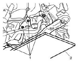
- Support front suspension frame and engine rear mounting member using jack (2).
- Carry out Step 1) to 12) of "Removal" under FRONT SUSPENSION FRAME, STABILIZER BAR AND/OR BUSHINGS REMOVAL AND INSTALLATION
in order to lower engine with front suspension frame.
- Remove front suspension frame mounting bolts (1).
 Courtesy of SUZUKI OF AMERICA CORP.
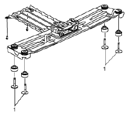
- Remove engine rear mounting member bolts (1).
 Courtesy of SUZUKI OF AMERICA CORP.
- Before lowering engine, recheck to make sure all hoses, electric wires and cables are disconnected from engine.
- Lower engine with transmission, transfer, front suspension frame and engine rear mounting member from engine compartment.
- Disconnect transmission from engine referring to MANUAL TRANSMISSION ASSEMBLY DISMOUNTING AND REMOUNTING
or AUTOMATIC TRANSMISSION UNIT COMPONENTS
, if necessary.
- Remove engine with engine front mounting bracket (1) from engine front mounting (2), if necessary.
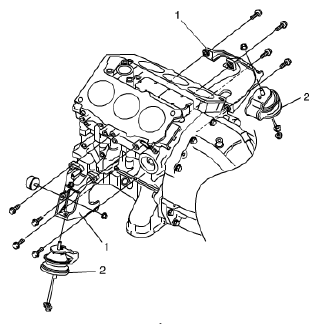 Courtesy of SUZUKI OF AMERICA CORP.
- Remove clutch cover and clutch disk referring to CLUTCH COVER, CLUTCH DISC AND FLYWHEEL REMOVAL AND INSTALLATION
, if necessary.