Pinout Values and Diagnostic Parameters
Inspection of 4WD Control Module and Its Circuits4WD control module and its circuits can be checked at coupler connected to 4WD control module by measuring voltage, pulse signal.
CAUTION: 4WD control module cannot be checked by itself. It is strictly prohibited to connect voltmeter or ohmmeter to 4WD control module with couplers disconnected from it.
Voltage and Signal Check
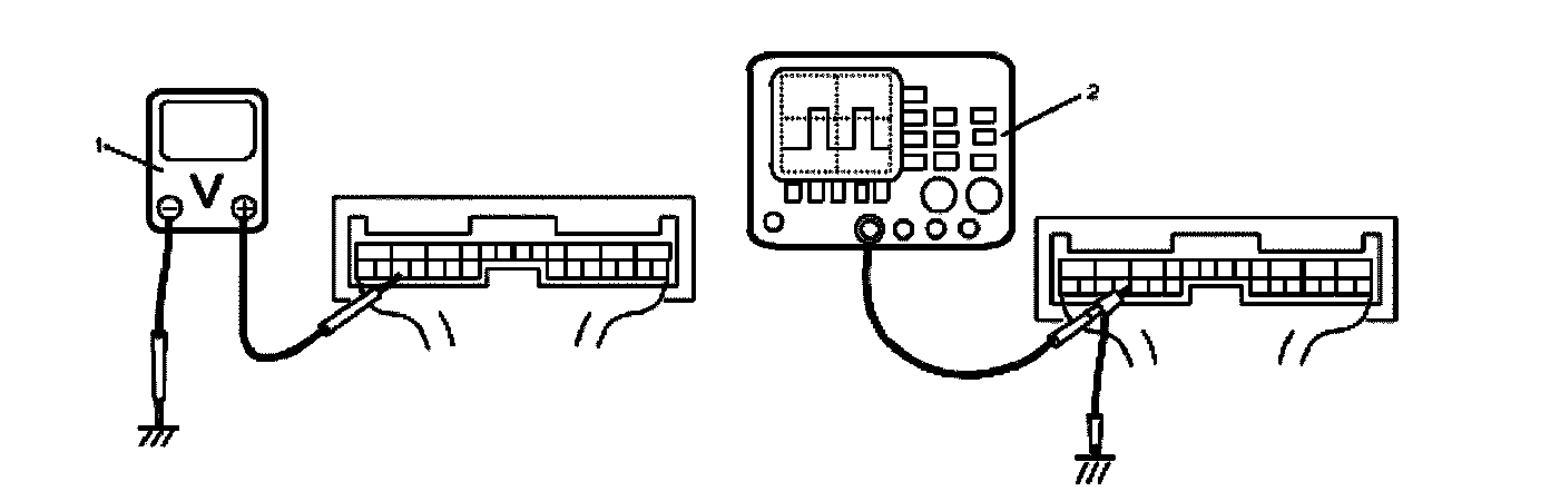
1. Check voltage using voltmeter (1) connected to each terminal of couplers.
2. Check signal using oscilloscope (2) connected to each terminal of couplers.
NOTE:
^ As each terminal voltage is affected by the battery voltage, confirm that it is 11 V or more when ignition switch is turned ON.
^ Pulse signal cannot be measured by voltmeter. It can be measured by oscilloscope.
^ Item with asterisk (*) in normal voltage column can be read only by oscilloscope.
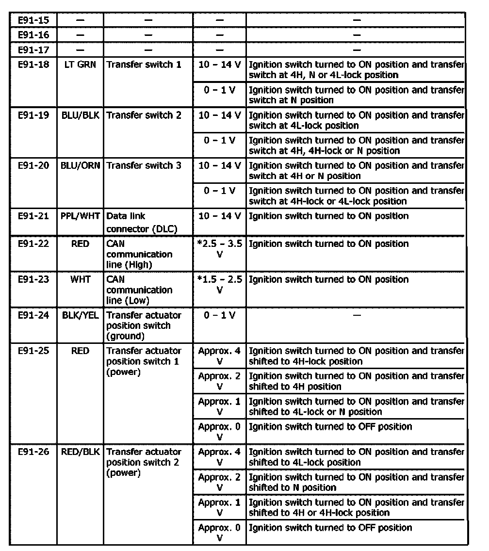
Terminal arrangement of 4WD control module connector (Viewed from harness side)
Terminal arrangement of 4WD control module connector (Viewed from harness side) (Part 1):
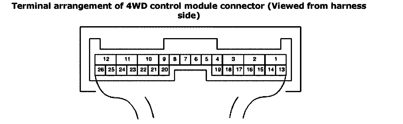
Terminal arrangement of 4WD control module connector (Viewed from harness side) (Part 2):
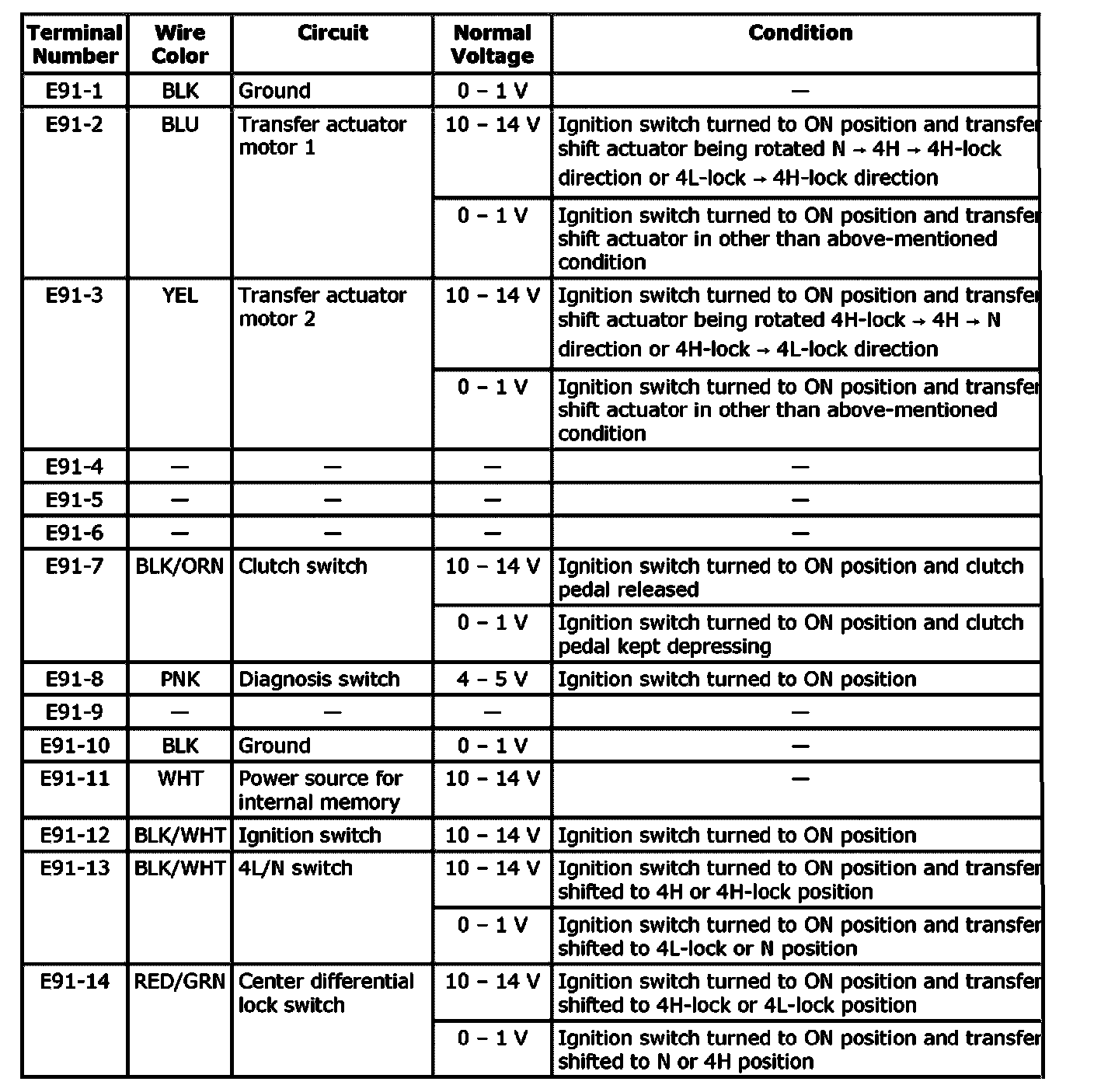
Terminal arrangement of 4WD control module connector (Viewed from harness side) (Part 3):