With Generic Scan Tool
DTC CheckNOTE: To know how to use SUZUKI scan tool in detail, refer to its operator's manual.
Using SUZUKI Scan Tool
1. Turn ignition switch to OFF position.
2. Connect SUZUKI scan tool to data link connector (DLC) (1) located on underside of instrument panel.
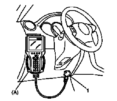
Special Tool
(A): SUZUKI scan tool
3. Apply light to sunload sensor vertically, holding incandescent lamp of approximately 100 W about 100 mm (3.94 in.) away from sunload sensor.
NOTE: If B1504 is detected when vehicle is not exposed to light (indoor, etc.), check again for DTC with light from incandescent lamp applied to sunload sensor, referring to Sunload Sensor Inspection. If B1504 is not detected in this check, sunload sensor is in good condition.
4. Turn ignition switch to ON position.
5. Read DTC according to instructions displayed on SUZUKI scan tool and print it or write it down. Refer to SUZUKI scan tool operator's manual for further details.
If communication between scan tool and ECM (PCM) is not possible, check if scan tool is communicable by connecting it to ECM (PCM) in another vehicle. If communication is possible in this case, scan tool is good condition. Then check data link connector and serial data line (circuit) in the vehicle with which communication was not possible.
6. After completing the check, turn ignition switch OFF position and disconnect SUZUKI scan tool from data link connector (DLC).
Not Using SUZUKI Scan Tool
NOTE: If B1504 is detected when vehicle is not exposed to light (indoor, etc.), check again for DTC with light from incandescent lamp applied to sunload sensor, referring to Sunload Sensor Inspection. If B1504 is not detected in this check, sunload sensor is in good condition.
1. Apply light to sunload sensor vertically, holding incandescent lamp of approximately 100 W about 100 mm (3.94 in.) away from sunload sensor.
2. Set the following selectors to specified positions respectively with turn ignition switch OFF.
- Temperature selector (1): max cool position
- Blower speed selector (2): "OFF" position
3. While pressing "B/L" (BI-LEVEL) switch (3) and "D/F" (defogger foot) switch (4) simultaneously turn ignition switch to ON position.
NOTE: For 15 seconds after ignition switch is turned on, both "REC" indicator lamp and "FRE" indicator lamp light for in-system trouble check.
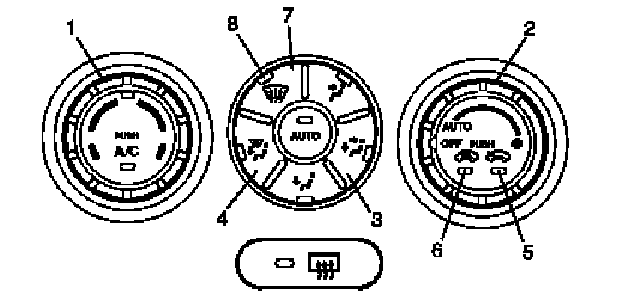
4. Read DTC from flashing pattern of "FRE" indicator (5) and "REC" indicator (6) referring to DTC Table.
NOTE:
- When more than one current DTC are detected, only current DTC having the highest priority is indicated. Therefore, after troubleshooting the malfunction, current DTC check has to be performed again to see if any other current DTC (s) is detected.
- Pressing "DEF" switch (7) alternates display of current DTC and history DTC.
- "DEF" indicator lamp (8) remains off when display is in current DTC mode and it lights up when display is in history DTC mode.
- When more than one history DTC are detected, the highest priority history DTC is shown. The second priority DTC can be shown by pressing air intake selector.
5. After completing above check, turn ignition switch to "OFF" position.
NOTE:
HVAC control module returns to a original state at the following conditions.
- Ignition switch turned to "OFF" position
- Temperature selector is operated
- Blower speed selector is operated
- 5 minutes have passed since HVAC control unit started DTC display